MGC+ Hardware and Installation Manual
2-39
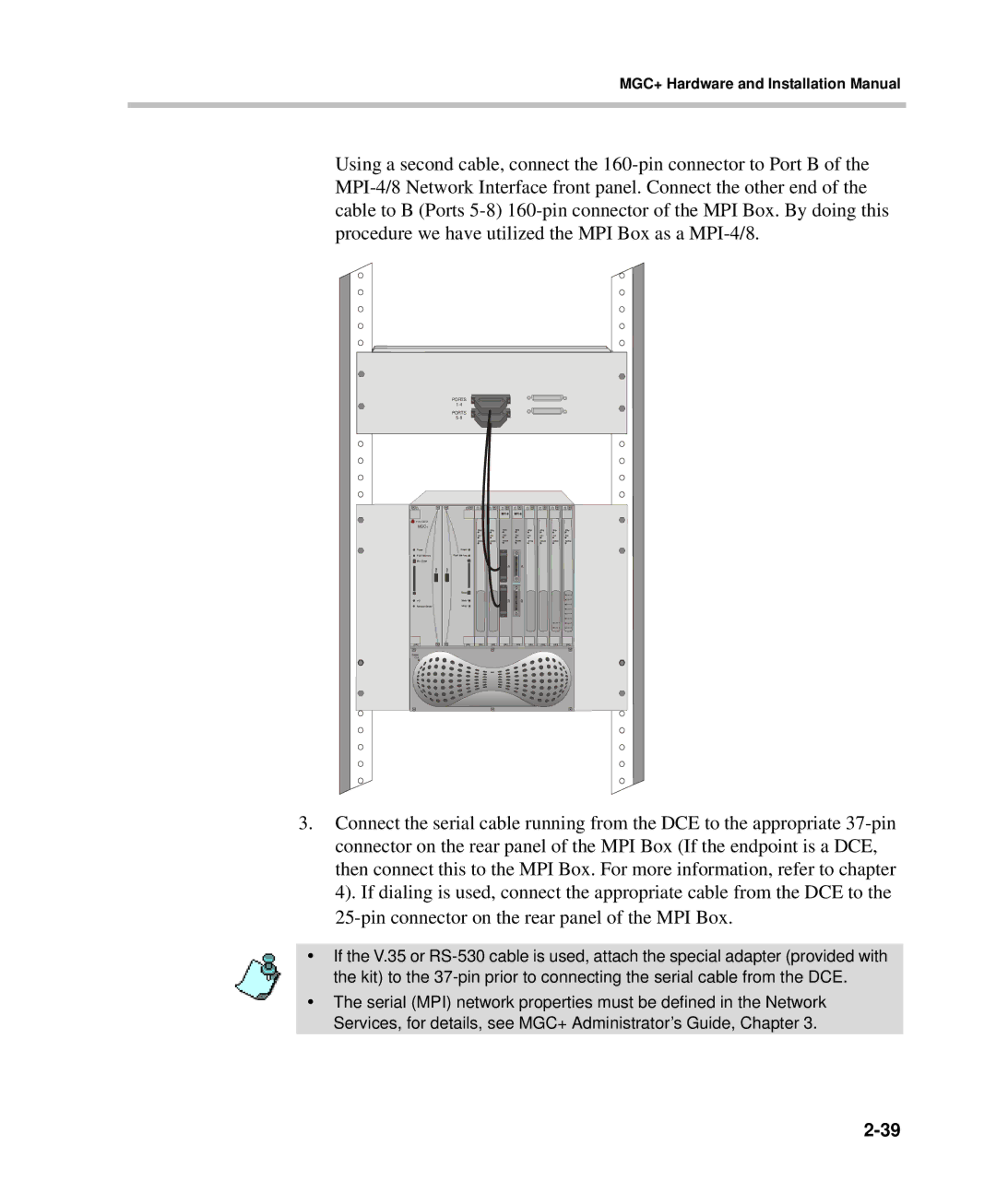
Using a second cable, connect the 160-pin connector to Port B of the
MPI-4/8 Network Interface front panel. Connect the other end of the
cable to B (Ports 5-8) 160-pin connector of the MPI Box. By doing this
procedure we have utilized the MPI Box as a MPI-4/8.
3. Connect the serial cable running from the DCE to the appropriate 37-pin
connector on the rear panel of the MPI Box (If the endpoint is a DCE,
then connect this to the MPI Box. For more information, refer to chapter
4). If dialing is used, connect the appropriate cable from the DCE to the
25-pin connector on the rear panel of the MPI Box.
Power
Out
POLYCOM
R
MGC+
Line 1
Line 2
Line 3
Line 1
Line 4
Line 2
Line 5
Line 6
Line 7
Line 8
PORTS
1-4
PORTS
5-8
A
B
A
B
If the V.35 or RS-530 cable is used, attach the special adapter (provided with
the kit) to the 37-pin prior to connecting the serial cable from the DCE.
The serial (MPI) network properties must be defined in the Network
Services, for details, see MGC+ Administrator’s Guide, Chapter 3.