Chapter 2 - Hardware Installation

To install the MPI-4/8 Network Interface Module:

1.Slide the MPI-8 Network Interface module into a free slot in the MCU front panel.

2.Push the MPI-8 Network Interface module firmly into the Backplane, making sure it is properly seated in its slot.

3.Tighten the screws on the front panel of the MGC+50 that secure the MPI-8 Network Interface module.

To mount the MPI Box on the Rack for the MGC+50:

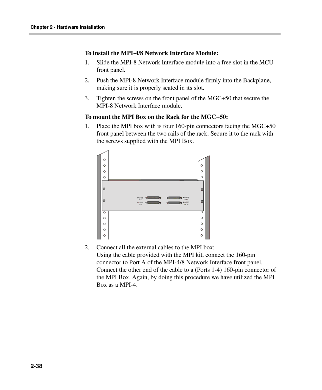
1.Place the MPI box with is four 160-pin connectors facing the MGC+50 front panel between the two rails of the rack. Secure it to the rack with the screws supplied with the MPI Box.

PORTS

PORTS

1-4

9-12

PORTS

PORTS

5-8

13-16

2.Connect all the external cables to the MPI box:

Using the cable provided with the MPI kit, connect the 160-pin connector to Port A of the MPI-4/8 Network Interface front panel. Connect the other end of the cable to a (Ports 1-4) 160-pin connector of the MPI Box. Again, by doing this procedure we have utilized the MPI Box as a MPI-4.
2-38

Page 58
Image 58
Polycom DOC2238A manual To install the MPI-4/8 Network Interface Module, To mount the MPI Box on the Rack for the MGC+50