MGC+ Hardware and Installation Manual
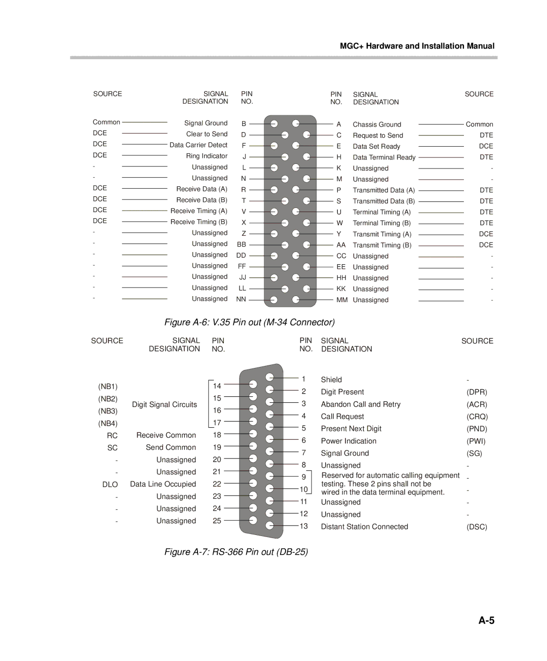
SOURCE | SIGNAL | PIN | PIN | SIGNAL | SOURCE |
| DESIGNATION | NO. | NO. | DESIGNATION |
|
Common | Signal Ground | B | A | Chassis Ground | Common |
DCE | Clear to Send | D | C | Request to Send | DTE |
DCE | Data Carrier Detect | F | E | Data Set Ready | DCE |
DCE | Ring Indicator | J | H | Data Terminal Ready | DTE |
- | Unassigned | L | K | Unassigned | - |
- | Unassigned | N | M | Unassigned | - |
DCE | Receive Data (A) | R | P | Transmitted Data (A) | DTE |
DCE | Receive Data (B) | T | S | Transmitted Data (B) | DTE |
DCE | Receive Timing (A) | V | U | Terminal Timing (A) | DTE |
DCE | Receive Timing (B) | X | W | Terminal Timing (B) | DTE |
- | Unassigned | Z | Y | Transmit Timing (A) | DCE |
- | Unassigned | BB | AA | Transmit Timing (B) | DCE |
- | Unassigned | DD | CC | Unassigned | - |
- | Unassigned | FF | EE | Unassigned | - |
- | Unassigned | JJ | HH | Unassigned | - |
- | Unassigned | LL | KK | Unassigned | - |
- | Unassigned | NN | MM | Unassigned | - |
Figure A-6: V.35 Pin out (M-34 Connector)
SOURCE | SIGNAL | PIN | ||
| DESIGNATION | NO. | ||
|
|
|
|
|
(NB1) |
| 14 |
| |
|
| |||
(NB2) | Digit Signal Circuits | 15 |
| |
| ||||
(NB3) | 16 |
| ||
|
| |||
(NB4) |
| 17 |
| |
|
| |||
|
|
|
|
|
RC | Receive Common | 18 |
| |
| ||||
SC | Send Common | 19 |
| |
| ||||
- | Unassigned | 20 |
| |
| ||||
- | Unassigned | 21 |
| |
| ||||
DLO | Data Line Occupied | 22 |
| |
| ||||
- | Unassigned | 23 |
| |
| ||||
- | Unassigned | 24 |
| |
| ||||
- | Unassigned | 25 |
| |
| ||||
PIN | SIGNAL | SOURCE | ||
NO. | DESIGNATION |
| ||
1 |
|
| Shield | - |
2 |
|
| Digit Present | (DPR) |
3 |
|
| Abandon Call and Retry | (ACR) |
4 |
|
| Call Request | (CRQ) |
5 |
|
| Present Next Digit | (PND) |
6 |
|
| Power Indication | (PWI) |
7 |
|
| Signal Ground | (SG) |
8 |
|
| Unassigned | - |
9 |
|
| Reserved for automatic calling equipment | - |
10 |
|
| testing. These 2 pins shall not be | - |
|
| wired in the data terminal equipment. | ||
|
| |||
11 |
| Unassigned | - | |
12 |
| Unassigned | - | |
13 |
| Distant Station Connected | (DSC) | |