Manuals
/
Polycom
/
Computer Equipment
/
Network Router
Polycom
DOC2238A
manual
shows the Video+ module architecture, Video+ Module Architecture
Models:
DOC2238A
1
121
160
160
Download
160 pages
8.7 Kb
118
119
120
121
122
123
124
125
Troubleshooting
Specs
Install
Alarms Port
Controls and Indicators
Connecting to the power source
Maintenance
SysConfig dialog box opens
Diagnostics MGC+50/MGC+100
MGC+ Power Do This Setting
Page 121
Image 121
MGC+ Hardware and Installation Manual
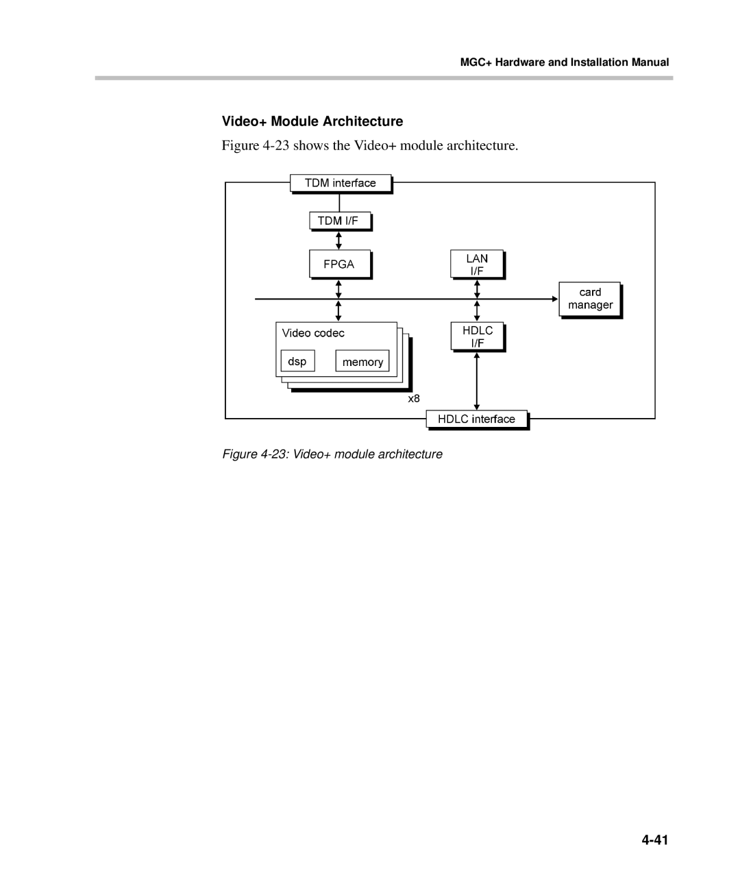
Video+ Module Architecture
Figure
4-23
shows the Video+ module architecture.
Figure
4-23:
Video+ module architecture
4-41
Page 120
Page 122
Page 121
Image 121
Page 120
Page 122
Contents
Version 9.0.4 August 2010 DOC2238A
Polycom MGC+50 MGC+100
USA
Table of Contents
System Architecture
Iii
Hardware Description
System Maintenance
MGC Hardware and Installation Guide
Table of Contents
Before You Begin
Before You Begin
MGC+ Unit Main Features
Physical MGC+50 MGC+100
MGC+50/MGC+100 Specifications
IP Protocols MGC+50/MGC+100
Protocols MGC+50/MGC+100
Serial
IP H.323 and SIP
External MGC+50/MGC+100 Communications
Local/Remote External MGC+50/MGC+100 Equipment
Diagnostics MGC+50/MGC+100
Conference Setup Scheduled Unscheduled MGC+50/MGC+100
Serviceability MGC+50/MGC+100 Reliability
Power Supply MGC+50 MGC+100
MGC+ Control Unit
Power Consumption MGC+50 MGC+100
Scope of Manual
Conventions
List of Abbreviations
Installation and Configuration Workflow
Installation and Configuration Workflow
Before You Begin
Hardware Installation
System Safety
MGC+100 Hardware Installation
Inspecting the MGC+/ReadiManager IAM Package Contents
General Safety Precautions
Polycom MGC+/ReadiManagerReadiManager Precautions
Rack Mount Safety Precautions
MGC+100 package
Unpacking and Positioning the MGC+100
Unpacking the MGC+100
Mounting the MGC+100 on a 23 Rack
Unscrew both MCU the side screws and remove both side plates
Mounting the MGC+100 on a 19 Rack
Shows how to mount the MGC+100 on the 19 rack
Item # Polycom P/N Description Quantity
Fit the flat washer Item #4 onto the screw
Contents of the MGC+ ReadiManager Server pre-installed on
Installing the ReadiManager IAM in the MGC+ Unit
Contents of the MGC+ ReadiManager Server Upgrade Package
Inspecting the MGC+ ReadiManager Server
MGC+ Power Do This Setting
MGC+ ReadiManager Installation
Shut Down button
Removing the Blank Panel from the MGC+ Unit
To remove the blank panel from the front of the MGC+ unit
Installing the I/O Card for the ReadiManager IAM
To install the I/O card for the ReadiManager IAM
Inserting the ReadiManager IAM into the MGC+ Unit
To insert the Polycom ReadiConvene IAM blade
MGC+100 Dongle
Connecting and Setting Up the MGC+100
To connect to the AC Inlet
Connecting to the power source
Connecting the MGC+100 to the LAN Network
To connect the MGC+100 to the Isdn network or T1-CAS Network
Connecting the MGC+100 to the Network
To connect the MGC+100 to the H.323 network
MPI-4/8 Hardware Installation for the MGC+100
11 MPI Box rack mounting options
To install the MPI-4/8 Network Interface Module
Turn OFF power to the MCU and unplug it from AC power
To install the MPI Box on Top of the MCU
Rear Front
MPI-8 MPI-8
Unpacking and Positioning the MGC+50
MGC+50 Hardware Installation
To unpack and position the MGC+50
13 Unpacking the MGC+50
Mounting the MGC+50 on a Rack
To install and mount the MGC+50
Front Remove plate
Screw mounting plate from the inside of the MGC+
MPI Box
MGC+50 Dongle
Connecting and Setting Up the MGC+50
To connect to the AC Inlet
Connecting the MGC+50 to the LAN Network
To connect the MGC+50 to the Isdn network and T1-CAS network
Connecting the MGC+50 to the Pstn Network
16 LAN H.323 network connection
Connecting the MGC+50 to the H.323 Network
17 MPI Box mounting option
MPI-4/8 Hardware Installation for the MGC+50
To mount the MPI Box on the Rack for the MGC+50
To install the MPI-4/8 Network Interface Module
Polycom
Xpek OS
Compact Flash Memory Use on the MGC+
Rescue Disk pSOS
Xpek
Swapping the Operating System OS
Initial ReadiConvene IAM Configuration
MGC+ Software Installation and Configuration
First Entry MGC+ Control Unit CU IP Configuration
Edit the file with the following text
Press 1, Change the MGC+ IP Setting
Properties button
MGC+ Hardware and Installation Manual
Hardware Installation
Type C\\mcu\cfgedit lan.cfg and press Enter
Method 3 Defining the IP address using a Keyboard and Mouse
To create a new Compact Flash boot file
Formatting and Creating a New Compact Flash Boot File
MGC+ Hardware and Installation Manual
Clocking
System Architecture
MGC+100 Components
Backplane Rear
MGC+ unit functional block diagram
MUX+ Module is not used with the H.323/SIP modules
Information Flow
System Architecture
MGC+ Manager Interface
Power Supply Flow
System Architecture
Hardware Description
Serial Bus port
MGC+100 Components Location
Main Switch
MGC+100 top internal view
MGC+50 front panel
MGC+50 Components Location
MGC+50 top inside view
Physical
ReadiManager IAM
Control Unit
Shows a block diagram of the Main Control Module
MGC+ Hardware and Installation Manual
MGC+100 Backplane
Backplane
MGC+50 Backplane
Control Bus
Information Highway
Powerplane
Power Module in the MGC+100
Power Supply Module
Voltage Maximum current Amp
Power Supply Cord
Power Module in the MGC+50
Circuit Breaker AC Power
MGC+ MGC+100
Fans
Alarms Port
Functional Module Port capacity
Functional Modules
IP+12/24
MPI-4
Functional Module Port capacity
Component Description
10 Net-2/Net-4/Net-8 ISDN/T1-CAS Network Interface Module
Net-2/Net-4/Net-8 or T1-CAS Network Interface Module
11 2/4/8 tri-color LED NET cards front panels
Net-2/Net-4/Net-8 ISDN/T1-CAS Network Interface Data Stream
IP+ cards are available with version 4.23 and higher
IP+ Network Interface Module
Module Port Capacity
RTP
IP+ Network Interface Module Architecture
14 MPI-4/8 Network Interface Module front panel
MPI-4/8 Network Interface Module
15 MPI box front panel
MPI-4/8 Network Interface Data Stream
When the MCU is set as a DTE
MCU DCE
When the MCU is set as a DCE
19 MPI-4/8 Network Interface module architecture
MPI Network Interface Module Architecture
Encryption requires the MUX+ card
MUX+ Module
21 MUX+ Card Participant Properties
MUX+ Card Properties
MUX+ Port Capacity
IVR/Greet & Guide Welcome Slide
MUX+40
MUX+ Participant Move Options
MUX+ Resource Report
MGC-50/100 Resource Report
IP/SIP
Audio+ Module
Audio+ Port Capacities
Audio+ Module Architecture
Audio Algorithm Card Type
Video+ Module
Video+ Module Architecture
23 shows the Video+ module architecture
Data Module Architecture
Data Module
Rear I/O Boards
Input/Output I/O Boards
Types of I/O cards on functional Modules
26 Isdn /T1-CAS Network connection for two spans
28 ISDN/T1-CAS Network connection for eight spans
Attaching the Music I/O Card to the Audio+ Module
Audio+ Music I/O Card
Rear
Enabling the Audio+ Music I/O Card in the MCU Software
SysConfig dialog box opens
MUX+ Video Slides
Hardware Description
System Maintenance
MGC+ Unit Front Panel
Controls and Indicators
LED Indicators
HD LED
Module Name Color Description
T1-CAS
Flashing
Module State
MGC+100 rear panel controls
MGC+ Unit Rear Panel
MGC+50 rear panel controls
Corrective Maintenance
Replacing the I/O Cards of Functional Modules
Replacing a Functional Module
Replacing the Power Supply Module on the MGC+50
Replacing the Power Supply Modules on the MGC+100
System Maintenance
PWR
System Maintenance
Fan Replacement for the MGC+100
Fan Replacement for the MGC+50
Replacing the Main Control Module
Replacing the Main Control Module rear I/O Panel
Replacing Compact Flash Accessories
Item # Polycom P/N Description
Replacing the Dongle
Verifying the Dongle
Shutting Down the MGC+ 50/100
Troubleshooting
PRI Port Assignment
Pin Signal Name
LAN PIN Assignment
Alarms Port Pin Assignment
Pin Description
RS-232 Pin Assignment
PIN Signal Designation
Serial Port Connectors Pin out Assignment
Figure A-6 V.35 Pin out M-34 Connector
Cables For the MPI-4/8 Network Interface Module
Top
Page
Image
Contents