MGC+ Hardware and Installation Manual
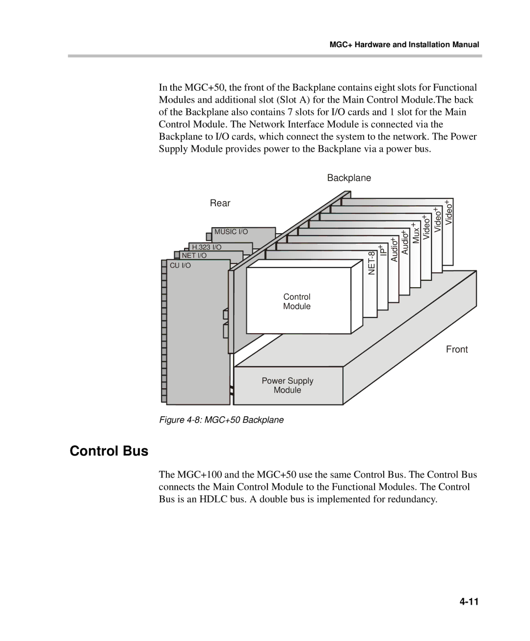
In the MGC+50, the front of the Backplane contains eight slots for Functional Modules and additional slot (Slot A) for the Main Control Module.The back of the Backplane also contains 7 slots for I/O cards and 1 slot for the Main Control Module. The Network Interface Module is connected via the Backplane to I/O cards, which connect the system to the network. The Power Supply Module provides power to the Backplane via a power bus.
Backplane
Rear
MUSIC I/O
H.323 I/O
![]()
![]() NET I/O
NET I/O
![]()
![]() CU I/O
CU I/O
Video+
Video+
Video+
Mux+
Audio+
Audio+
IP+
![]() NET-8
NET-8
Control
Module
Front
Power Supply
Module
Figure 4-8: MGC+50 Backplane
Control Bus
The MGC+100 and the MGC+50 use the same Control Bus. The Control Bus connects the Main Control Module to the Functional Modules. The Control Bus is an HDLC bus. A double bus is implemented for redundancy.