MGC+ Hardware and Installation Manual
Connecting and Setting Up the MGC+100
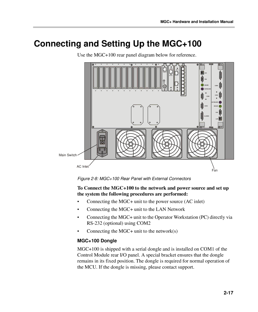
Use the MGC+100 rear panel diagram below for reference.
Main Switch
DEBUG | LAN |
|
|
| |
| VGA |
|
| MOUSE | COM2 |
LINE IN | KEYBOARD |
|
| COM1 | COM1 |
|
| |
|
| KEYBOARD |
| COM2 | MOUSE |
|
| VGA |
| ALARMS |
|
|
| LAN |
AC Inlet
Fan
Figure 2-8: MGC+100 Rear Panel with External Connectors
To Connect the MGC+100 to the network and power source and set up the system the following procedures are performed:
•Connecting the MGC+ unit to the power source (AC inlet)
•Connecting the MGC+ unit to the LAN Network
•Connecting the MGC+ unit to the Operator Workstation (PC) directly via
•Connecting the MGC+ unit to the network(s)
MGC+100 Dongle
MGC+100 is shipped with a serial dongle and is installed on COM1 of the Control Module rear I/O panel. A special bracket ensures that the dongle remains in its fixed position. The dongle is required for normal operation of the MCU. If the dongle is missing, please contact support.