Chapter 5 - System Maintenance
9.Slide in the replacement Power Supply Module from the front panel and push it firmly into its place.
10.Tighten the six screws on the front panel of the MGC+50 that secure the Power Supply Module.
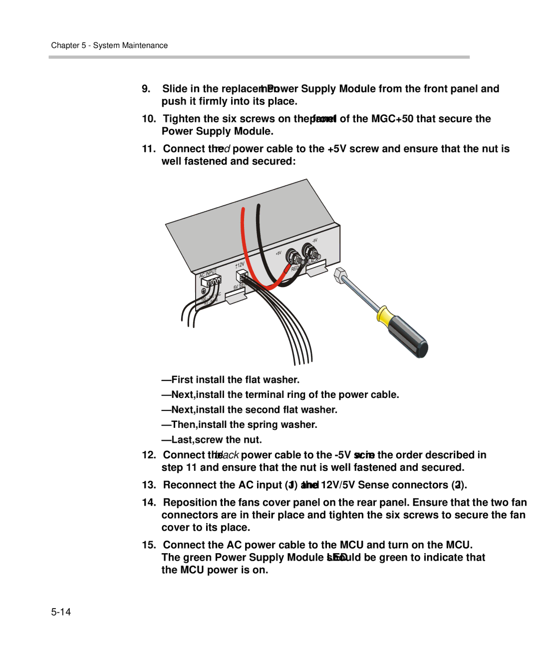
11.Connect the red power cable to the +5V screw and ensure that the nut is well fastened and secured:
—First install the flat washer.
—Next, install the terminal ring of the power cable.
—Next, install the second flat washer.
—Then, install the spring washer.
—Last, screw the nut.
12.Connect the black power cable to the
13.Reconnect the AC input (J1) and the 12V/5V Sense connectors (J2).
14.Reposition the fans cover panel on the rear panel. Ensure that the two fan connectors are in their place and tighten the six screws to secure the fan cover to its place.
15.Connect the AC power cable to the MCU and turn on the MCU.
The green Power Supply Module LED should be green to indicate that the MCU power is on.