MGC+ Hardware and Installation Manual
IP+ Network Interface Module Architecture
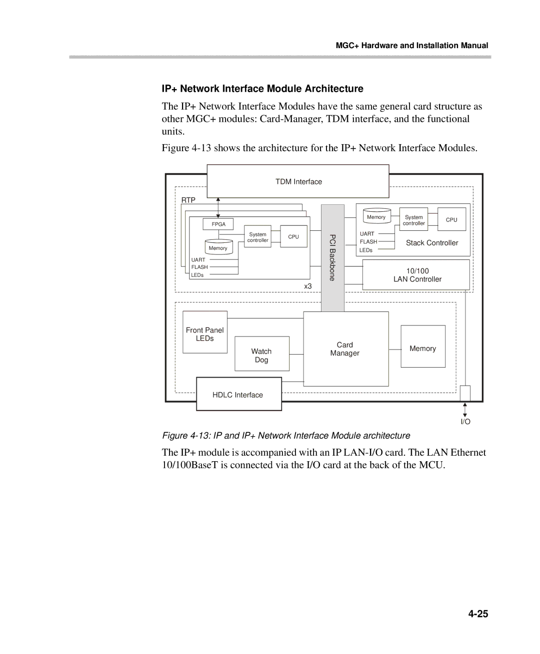
The IP+ Network Interface Modules have the same general card structure as other MGC+ modules:
Figure 4-13 shows the architecture for the IP+ Network Interface Modules.
| TDM Interface |
|
|
|
| |
RTP |
|
|
|
|
| |
|
|
| Memory | System | CPU | |
FPGA |
|
|
| controller | ||
|
|
|
| |||
System | CPU | PCI | UART |
|
| |
controller | FLASH | Stack Controller | ||||
| ||||||
Memory |
| |||||
| Backbone | LEDs |
|
| ||
|
|
|
| |||
UART |
|
|
|
| ||
|
|
|
|
| ||
FLASH |
|
|
| 10/100 |
| |
LEDs |
|
|
|
| ||
|
|
| LAN Controller |
| ||
| x3 |
|
|
| ||
|
|
|
|
| ||
Front Panel |
|
|
|
|
| |
LEDs |
| Card |
|
|
| |
Watch |
|
| Memory |
| ||
| Manager |
|
| |||
|
|
|
| |||
Dog |
|
|
|
|
| |
HDLC Interface |
|
|
|
|
| |
|
|
|
|
| I/O | |
Figure 4-13: IP and IP+ Network Interface Module architecture
The IP+ module is accompanied with an IP