MGC+ Hardware and Installation Manual
When the MCU is set as a DCE
The serial data stream flows from the endpoint (DTE) through the serial connector entering the MPI box by way of the
The network clock is enabled only when the span coming from the DCE to the MCU is active (i.e. handles a call). Therefore, the spans defined as Primary and Backup clock must be connected first when starting a conference and disconnected last when terminating the conference.
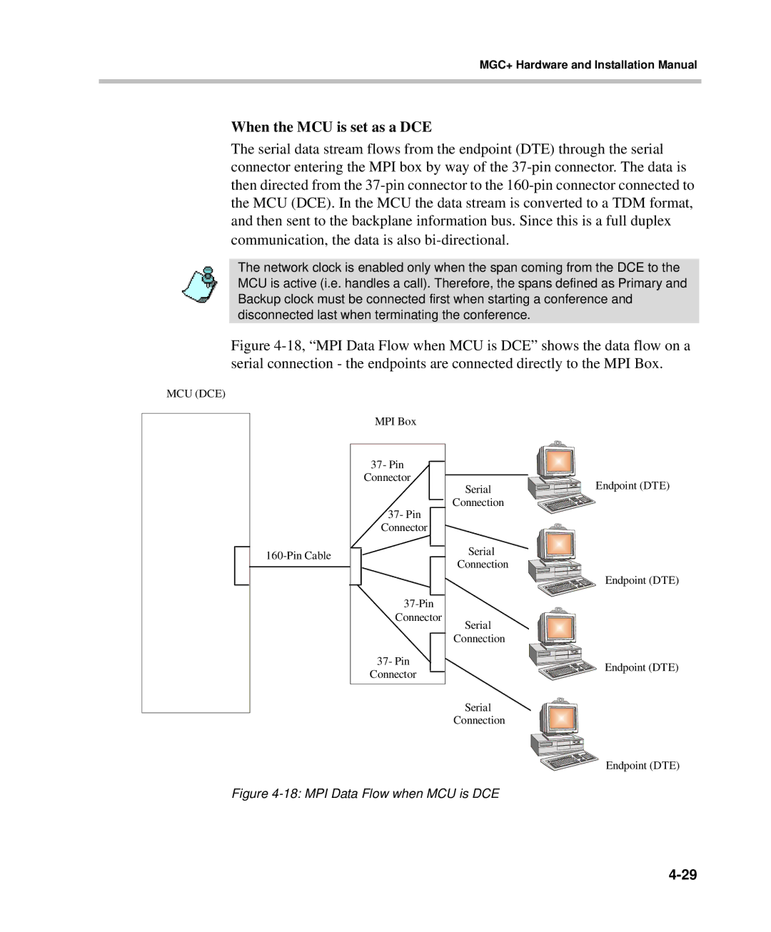
Figure 4-18, “MPI Data Flow when MCU is DCE” shows the data flow on a serial connection - the endpoints are connected directly to the MPI Box.
MCU (DCE)
MPI Box
| 37- Pin |
|
| Connector | Serial |
|
| |
| 37- Pin | Connection |
|
| |
| Connector |
|
| Serial | |
| Connection | |
|
| |
|
| |
| Connector | Serial |
|
| |
|
| Connection |
| 37- Pin |
|
| Connector |
|
|
| Serial |
|
| Connection |
Figure 4-18: MPI Data Flow when MCU is DCE
Endpoint (DTE)
Endpoint (DTE)
Endpoint (DTE)
Endpoint (DTE)