Polycom DOC2238A manual Rear Front

Models: DOC2238A

1 160
Download 160 pages 8.7 Kb
Page 44
Image 44

Chapter 2 - Hardware Installation

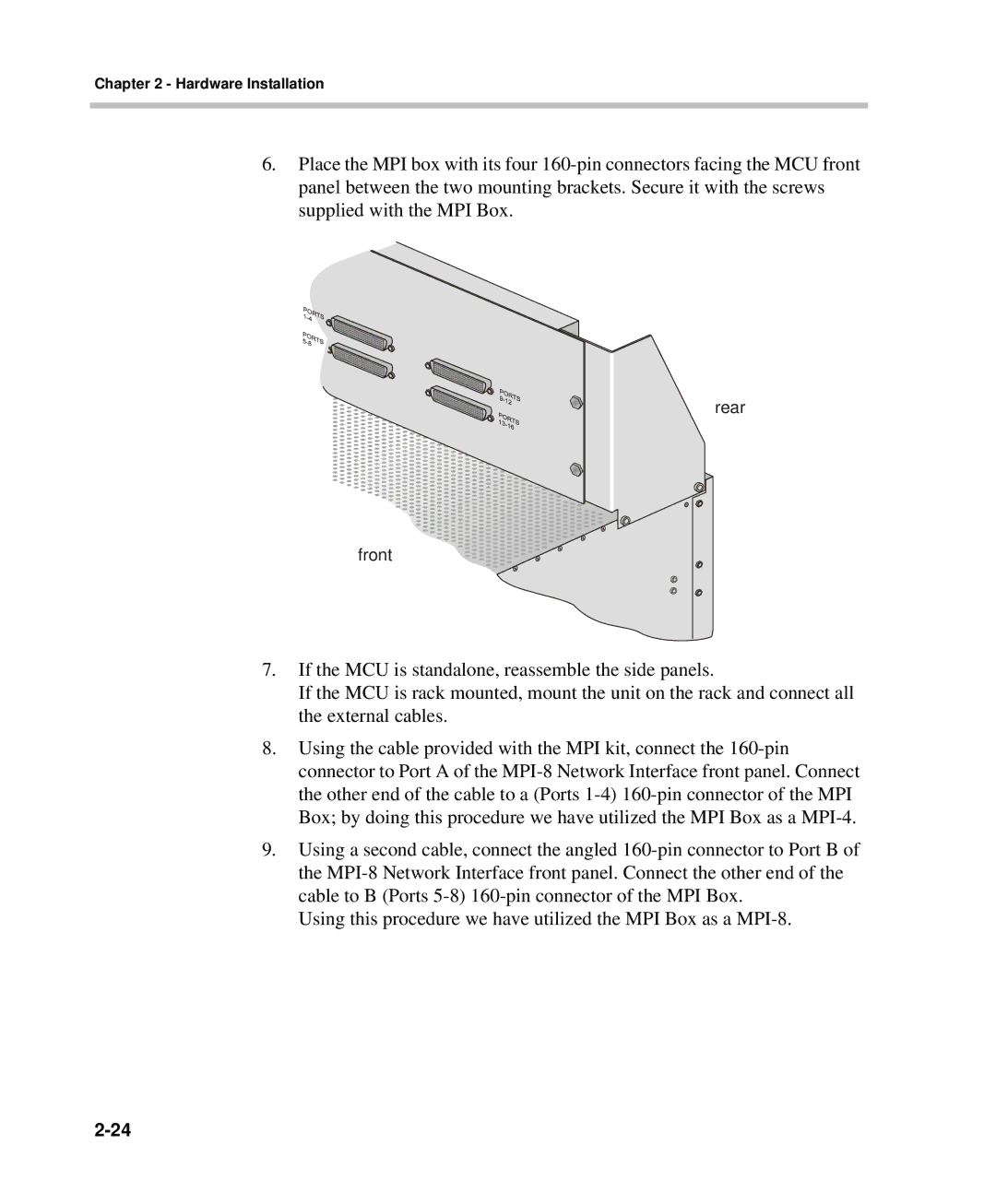
6.Place the MPI box with its four 160-pin connectors facing the MCU front panel between the two mounting brackets. Secure it with the screws supplied with the MPI Box.

rear

front

7.If the MCU is standalone, reassemble the side panels.

If the MCU is rack mounted, mount the unit on the rack and connect all the external cables.

8.Using the cable provided with the MPI kit, connect the 160-pin connector to Port A of the MPI-8 Network Interface front panel. Connect the other end of the cable to a (Ports 1-4) 160-pin connector of the MPI Box; by doing this procedure we have utilized the MPI Box as a MPI-4.

9.Using a second cable, connect the angled 160-pin connector to Port B of the MPI-8 Network Interface front panel. Connect the other end of the cable to B (Ports 5-8) 160-pin connector of the MPI Box.

Using this procedure we have utilized the MPI Box as a MPI-8.

2-24

Page 44
Image 44
Polycom DOC2238A manual Rear Front