3
System Architecture
The MGC+ unit is designed to provide maximum reliability, minimum interruptions, and effortless maintenance. Removable active components are accessed via the front panel to provide quick and easy serviceability. Redundant power supplies are easily accessed via the front panel, ensuring a fail safe operation (the MGC+50 power supply is not redundant, therefore not
All Functional Modules are
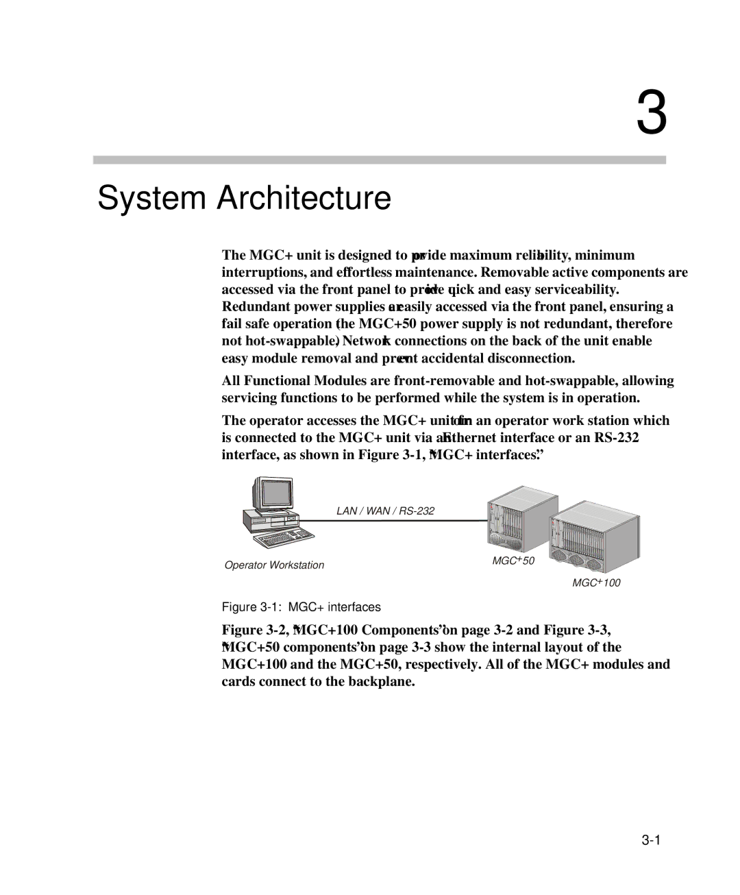
The operator accesses the MGC+ unit from an operator work station which is connected to the MGC+ unit via an Ethernet interface or an
| LAN / WAN / |
Operator Workstation | MGC+50 |
|
MGC+100