MGC+ Hardware and Installation Manual
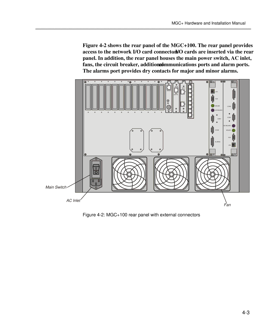
Figure 4-2 shows the rear panel of the MGC+100. The rear panel provides access to the network I/O card connectors. I/O cards are inserted via the rear panel. In addition, the rear panel houses the main power switch, AC inlet, fans, the circuit breaker, additional communications ports and alarm ports. The alarms port provides dry contacts for major and minor alarms.
Main Switch
DEBUG | LAN |
|
|
| |
| VGA |
|
| MOUSE | COM2 |
LINE IN | KEYBOARD |
|
| COM1 | COM1 |
|
| |
|
| KEYBOARD |
| COM2 | MOUSE |
|
| VGA |
| ALARMS |
|
|
| LAN |
AC Inlet
Fan