MGC+ Hardware and Installation Manual
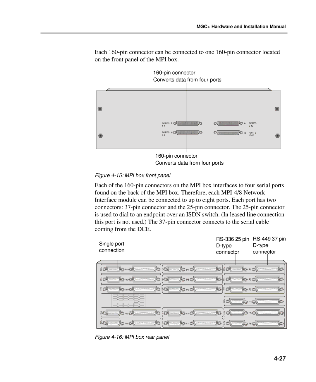
Each
Converts data from four ports
PORTS A | A | PORTS |
| ||
PORTS B | B | PORTS |
|
Converts data from four ports
Figure 4-15: MPI box front panel
Each of the
Single port | ||
| ||
connection | connector | connector |
DIAL | P12 | DIAL | P7 | DIAL | P1 |
DIAL | P13 | DIAL | P8 | DIAL | P2 |
DIAL | P14 | DIAL | P9 | DIAL | P3 |
P1 | P6 | P11 |
|
|
|
P2 | P7 | P12 |
|
|
|
P3 | P8 | P13 |
| DIAL | P4 |
|
| P14 |
| ||
P4 |
|
|
| ||
P9 | P15 |
|
|
| |
P5 | P10 | P16 |
|
|
|
DIAL | P15 | DIAL | P10 | DIAL | P5 |
DIAL | P16 | DIAL | P11 | DIAL | P6 |