Chapter 4 - Hardware Description
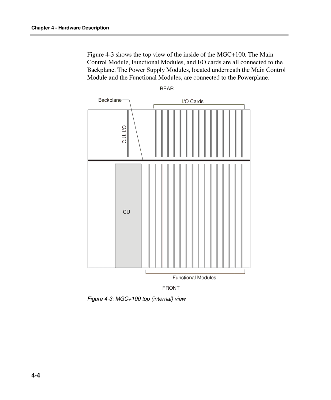
Figure 4-3 shows the top view of the inside of the MGC+100. The Main Control Module, Functional Modules, and I/O cards are all connected to the Backplane. The Power Supply Modules, located underneath the Main Control Module and the Functional Modules, are connected to the Powerplane.
|
|
| REAR | |||||||||||||||
Backplane |
|
|
|
| I/O Cards | |||||||||||||
|
|
|
|
|
|
|
|
|
|
|
|
|
|
|
|
|
|
|
|
|
|
|
|
|
|
|
|
|
|
|
|
|
|
|
|
|
|
C.U. I/O |
|
|
|
|
|
|
|
|
|
|
|
|
|
|
|
|
|
|
|
|
|
|
|
|
|
|
|
|
|
|
|
|
|
|
|
|
|
CU
Functional Modules
FRONT