MGC+ Hardware and Installation Manual
![]() POLYCOM
POLYCOM![]() MGC+
MGC+
Power
Out
| Line 1 |
| Line 2 |
| Line 3 |
| Line 4 |
| Line 5 |
| Line 6 |
Line 1 | Line 7 |
Line 2 | Line 8 |
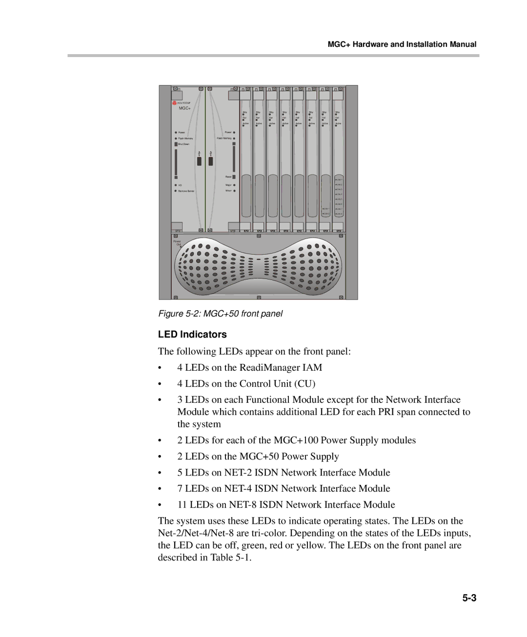
Figure 5-2: MGC+50 front panel
LED Indicators
The following LEDs appear on the front panel:
•4 LEDs on the ReadiManager IAM
•4 LEDs on the Control Unit (CU)
•3 LEDs on each Functional Module except for the Network Interface Module which contains additional LED for each PRI span connected to the system
•2 LEDs for each of the MGC+100 Power Supply modules
•2 LEDs on the MGC+50 Power Supply
•5 LEDs on
•7 LEDs on
•11 LEDs on
The system uses these LEDs to indicate operating states. The LEDs on the