Installation and Initialization |
|
| |
|
|
vertically polarized internal antenna, and connector 2 corresponds to the horizontally polarized internal antenna. Plugging an external antenna in to the antenna connector disables the corresponding internal antenna.
The AP continues to support antenna diversity with external antennas connected. With one external antenna connected to one of the two antenna connectors, one internal antenna and one external antenna are used for antenna diversity. With two external antennas connected, both external antennas are used for antenna diversity, and both internal antennas are disabled.
With external antennas connected, you may wish to manually select a particular antenna for use. To do so, disable antenna diversity by manually selecting which antenna to use through the Command Line Interface. See Configure Antenna Diversity for information.
NOTE: Using two external antennas is not recommended.
For a list of recommended antennas, see http://www.proxim.com/products/wifi/accessories. For installation instructions, see Installing External Antennas.
Active Ethernet
The
•The Active Ethernet (AE) integrated module receives ~48 VDC over a standard Category 5 Ethernet cable.
•To use Active Ethernet, you must have an AE hub (also known as a power injector) connected to the network.
•The cable length between the AE hub and the Access Point should not exceed 100 meters (approximately 325 feet). The AE hub is not a repeater and does not amplify the Ethernet data signal.
•If connected to an AE hub and an AC power simultaneously, the Access Point draws power from Active Ethernet.
Also see Hardware Specifications.
NOTE: The AP’s
LED Indicators
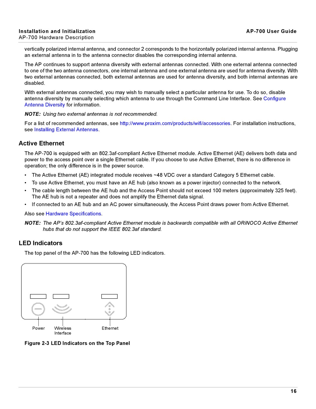
The top panel of the
|
|
|
|
|
|
Power | Wireless | Ethernet | |||
|
| Interface |
|
| |
Figure 2-3 LED Indicators on the Top Panel
16
