Preparations
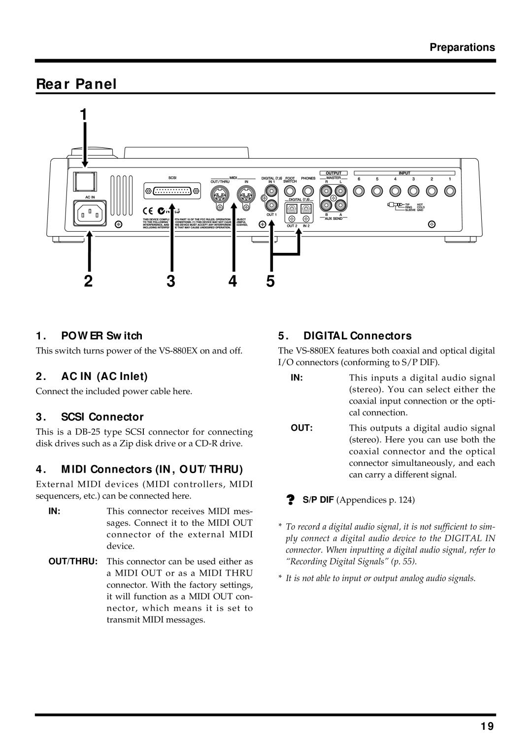
Rear Panel
1
2 | 3 | 4 | 5 |
1.POWER Switch
This switch turns power of the
5.DIGITAL Connectors
The
2.AC IN (AC Inlet)
Connect the included power cable here.
3.SCSI Connector
This is a
4.MIDI Connectors (IN, OUT/THRU)
External MIDI devices (MIDI controllers, MIDI sequencers, etc.) can be connected here.
IN:This connector receives MIDI mes- sages. Connect it to the MIDI OUT connector of the external MIDI device.
OUT/THRU: This connector can be used either as a MIDI OUT or as a MIDI THRU connector. With the factory settings, it will function as a MIDI OUT con- nector, which means it is set to transmit MIDI messages.
IN:This inputs a digital audio signal (stereo). You can select either the coaxial input connection or the opti- cal connection.
OUT: This outputs a digital audio signal (stereo). Here you can use both the coaxial connector and the optical connector simultaneously, and each can carry a different signal.
S/P DIF (Appendices p. 124)
*To record a digital audio signal, it is not sufficient to sim- ply connect a digital audio device to the DIGITAL IN connector. When inputting a digital audio signal, refer to “Recording Digital Signals” (p. 55).
*It is not able to input or output analog audio signals.
19
