L A F AG
A c c
AC .VC,}C [:]
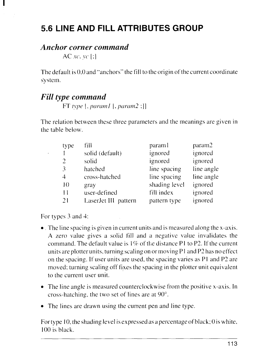
The default is (),0and “anchors” the fill to the origin of the current coordinate system.
F t c
FT t>p{ [. Il(tl%ll}l] [, p~1ra1n2:]]
The relation between lhese three parameters and the meanings are given in the table below.
type | fill | param 1 | param2 |
1 | solid (default) | ignored | ignored |
‘2 | solid | ignored | ignored |
3 | hatched | line spacing | line angle |
4 | line spucing | line angle | |
1() | gray | shading level | ignored |
II | fill index | ignored | |
21 | LaserJet III pattern | pattern type | ignored |
For types 3 and 4:
●The Iine spacing is gi}en in current units und is measured along the
A zero value gives a solid fill and a negtitivc value invalidates the command. The default value is I% of t clist~nceP I to P2. If [he current units are plotter units. turning scaling on or moving P 1and P2 has no effect on the spacing. If user units are used, the spacing varies as P I and P2 are moved: turning scaling off fi,xesthe spacing in the plotter unit equivalent to the current user unit.
. The line angle is measured counterclockwise from the positive
. The lines are drawn using the current pen and line type.
For type 10,the shading level isexpressed as a percentage of bkrck;Ois white. 100 is black.
113
