TimeProvider 1000 and 1100 Edge Clock
Symmetricom, Inc
Contents
Engineering and Ordering Procedures
Provisioning the TimeProvider
Testing the TimeProvider
Maintaining and Troubleshooting the TimeProvider
Index
Figures
TimeProvider User’s Guide
Tables
TimeProvider User’s Guide
This Preface
How to Use This Guide
Who Should Read This Guide
Purpose of This Guide
Structure of This Guide
Chapter, Title Description
Conventions Used in This Guide
When text appears It means This way
TimeProvider User’s Guide
Related Documents and Information
Added Provisioning Snmp Parameters, on
This Chapter
Overview of the TimeProvider
Shelves
Overview
TimeProvider 1000 ETSI-style Shelf
Expansion Panel
Outputs
Inputs
Operating Modes
SSU Mode
Communication
Clocks
PRR Mode
SUB Mode
Performance Monitoring
Mtie Calculations
Phase Measurements
Tdev Calculations
Ffoff Calculations
NTP Operation
NTP Operation
Physical Description
Snmp Simple Network Management Protocol
GPS
Connector Input Output Modules
Functional Description
Input Module
Shelf
Information Management Card IMC
Input/Output and Clock Module IOC
IOC Type Max Power W Typical Power W
System Power
Output Module
Expansion Panel
Communication Ports
Reference Input Signals
Ethernet
Local Craft Serial Port
Selecting the Input
Revertive Switching
Input State
Quality Level and Priority Level
SSMs and Quality Level
Sequence QLevel on Active Reference
Subtending Mode
Non-Revertive
Non-Revertive1 Revertive2
GPS Inputs
LOS INP2 INP1
Clock Performance
Output Signals
Retimer Modules
Synchronization Status Messages SSMs
Alarms
Description Quality Level Abbreviation
Output SSMs
Input SSMs
BesTime
SmartClock
GPS Holdover
Normal Tracking
Engineering and Ordering Procedures
Model 1100 Rear Access
Model 1000 Front Access
Front Access
Shelf
Input Modules
Rear Access
Output Modules
Part Number Description
IMC
IMC and IOC Modules
GPS Antenna
Part Number Description
Ordering the Cable Management Option
Ordering and Parts List
Ordering an NTP or Snmp License
Model Outputs Part Number
Ordering an NTP or Snmp License
Installing the TimeProvider
Getting Started
Pre-Installation Check
Performing a Site Survey
Physical Space
Environmental Requirements
Gathering the Tools
Rack Mounting
Unpacking the Unit
Main Shelf
Cable Management Tray
Rack Mounting
Rack Mounting
Rear Access Shelf
Front Access Shelf
Making Connections
Making Ground Connections
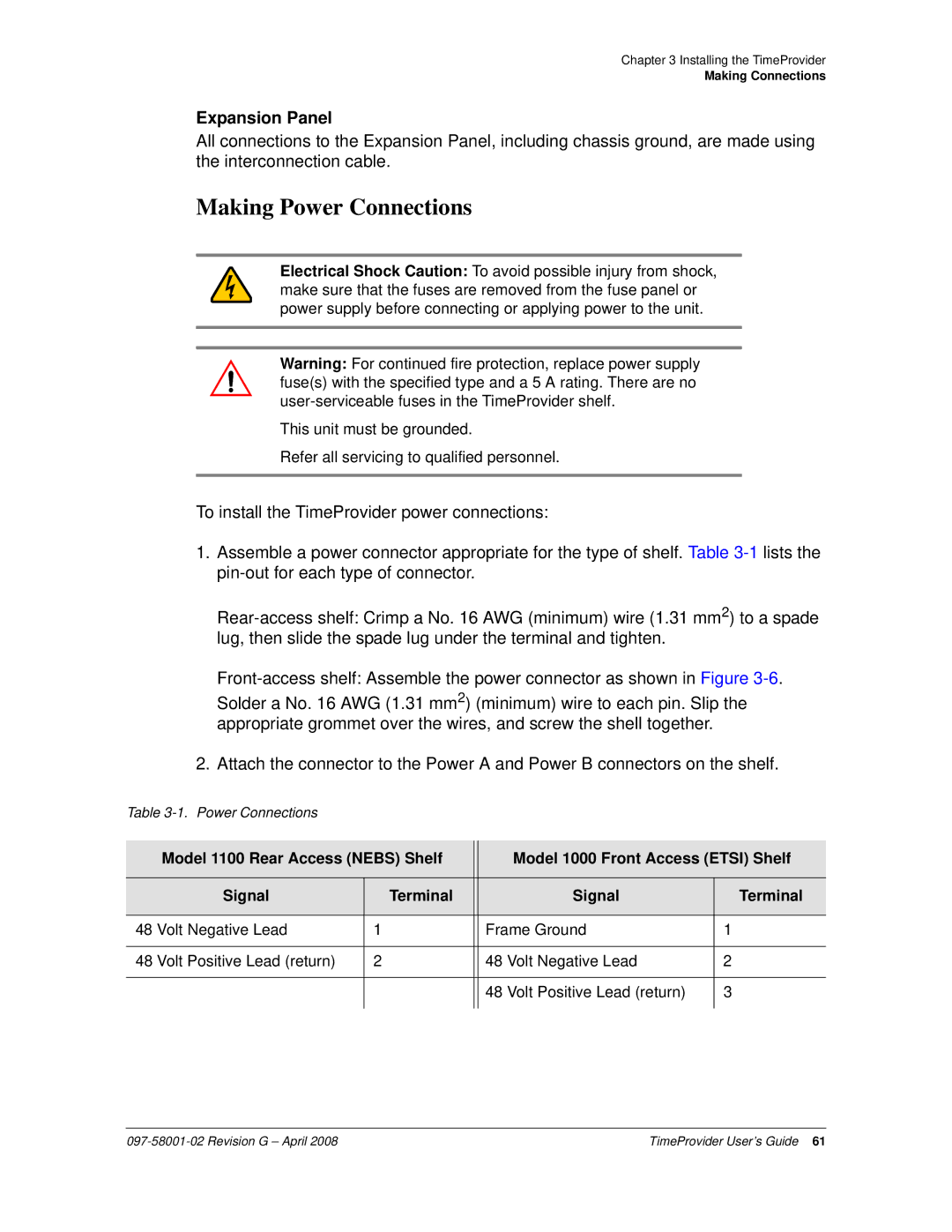
Making Power Connections
Rear Access Shelf Front Access Shelf
Verifying Power and Grounding Connections
Item Number Description Alarm Connector Reference
Installing the Input Module
Making Input Connections
Pin Description
Pinout for the DB9 Input module is shown in Table
10. BT43 Input Module
Connector Output Module Pin Description
Installing the Output Module
Making Output Connections
Item Number Description Reference
12. BNC and Wire-Wrap Output Modules
14. BT43 and Metric Siemens Output Modules
17. Sample Installation Schematic for a Retimer
Making Retimer Connections
Making Alarm Connections
Making GPS Connections
Installing the GPS Antenna
Making Connections
20. Antenna-to-Shelf Cabling
21. Installing the Antenna Bracket on a Pipe
23. Attaching the Antenna to the Bracket
Assemble the lightning suppressor as shown in Figure
Installing the Tpiu
Installing the Integrated IMC/TPIU
26. Mounting the Tpiu with a Model 1000 ETSI-Style Shelf
Local Craft Connector Remote Connector Signal Pin
Connecting to the Local Craft and Remote Serial Ports
Making Communications Connections
Changing Communications Settings
Installing Connections to the Ethernet Port
Direct Ethernet Connection
Name Pin
Network Connection
Powering Up the Shelf
Installation Check List
Working With Cards
Properly Handling Cards
Removing Cards
Inserting Cards
IMC Release IOC Release Features Added
Firmware Features
NTP
IMC/TPIU
Provisioning the TimeProvider
Symbol Description
TL1 Command Structure
TL1 Overview
TL1 Response Format
Error Response
Normal Response
In-Process Response
Autonomous Messages
Starting the TimeProvider for the First Time
LED Indications on Power-up
Powering Up the TimeProvider
Changing the Echo Mode
Logging In for the First Time
Setting the Response Format
Setting the Source ID sid
Setting the Date and Time
Setting RS-232 Parameters
Setting Communications Parameters
Setting Ethernet Parameters
Setting User Security
Setting the Echo Mode
Setting the Handshaking Flow Mode
Setting the IP Addresses
Setting Ethernet Parameters
Aid Keyword Value Description Default
Checking Communication Links
Defining the Security Parameters
Ping
Retrieve Header
TimeProvider Access Levels
Defining a User at the Security Access Level
Managing the User List
Adding a User at the Security Access Level
Logging
Logging
Parameter Uid Value Description
Logging Out
Uid Value Description
Adding a User
Admin Security
Parameter Value Description
None User
Displaying a User’s Access Level
Changing the Current User’s Password
Keyword Value Description
Parameter Description
None User Admin Security
Editing a User’s Access Level
Acclvl None User Admin Security
Response Value Description
Retrieving Current Users
Deleting a User
Starting SynCraft
Using SynCraft
Create New Connection Window
Creating a Connection
Closing a Connection
Opening a Connection
Setting the System Mode
Setting the System Mode
Keyword Value Description Default value
Provisioning the IOC
Sysmode SUB
Retrieving the Current System Mode
PRR
Setting the IOC Parameters
PRS Instate Enable
Setting the Input State
GPS = Disable
Provisioning the Input Reference
Setting the GPS Parameters
Setting the Input Frame Type
Setting the Input Frequency
PRS Frmtype
Automatic Return to a Higher Priority Reference
Controlling Automatic Reference Switching
CCS D4 ESF
JCC JCC4
Enabling Automatic Switching
Setting the Input Quality Level
SYS Refmode Auto Forced
Setting the Input Priority Level
SYS Inpref GPS PRS INP1
Manually Selecting the Reference
Provisioning the SSM
Ssmena Enable
Reading SSMs
Defining the SSM Bit Position
Setting Mtie and Ffoff Thresholds
Using Performance Monitoring
Crcena Enable
Enabling CRC4
MTIE-100 MTIE-500
Aid Keyword Value Description
Provisioning the Outputs
Setting Alarm Levels for Performance Monitoring Faults
GPS, PRS Mtie NR NA MN MJ CR
INP1, INP2
Enabling and Disabling the Outputs
Outstate Enable
Provisioning the Output Framing Type
D4 ESF CC JCC JCC4 ISOLATED1
Enabling and Disabling the Retimers
Provisioning Retimer Parameters
Rtmstate Enable
Rtmlbo
Provisioning the LBO
Provisioning NTP Parameters
Provisioning Cut-thru Mode
Freeflt Cutthru
Retime
Editing NTP Peer Server Parameters
Activating NTP
Enabling NTP Authentication
Aid Parameter Value Description Default value
Setting the NTP Authentication Key
Provisioning the Alarm Levels
Provisioning Alarms
Aid = IMC
Levels Default Editable? Mode Aid = SYS
Aid = IOC
Aid = PRS
Levels Default Editable? Mode
Inpais
Levels Default Editable? Mode Aid = INP1 or INP2
Inpoof
Inpql
Provisioning System-Level Alarms
SYS Elevtime Enable Disable
Retrieving Current Alarm Settings
SYS Gpsclrdel
Aid Keyword Description
Field Description
Retrieving Current Alarms
SYS IMC
Aid Description
Value Description
Aid Description ALL or null Access Identifiers
Displaying Alarm Status
Clearing the Office Audible Alarm
Clearing Alarms
IOC2TO1COMM-OK IOC2TO1COMM-FAIL
IMC2COMM-OK IMC2COMM-FAIL
Activating Snmp
Provisioning Snmp Parameters
Changing a User’s Security Parameters
Setting Up Snmp Traps, Informs, and Notifications
Displaying the Connected Users
Snmp
Displaying Events
System Commands
IOC EVT
GPS PRS ALM
Response Description
Displaying the Configuration of the TimeProvider
Restarting the TimeProvider
IMC Reset
SYS Factory
Electronically Backing up Provisioning Data
Saving Provisioning Data
Provisioning Worksheet
Section Parameter User-Defined Value
QLEVEL, INP1 QLEVEL, INP2 QLEVEL, GPS
QLEVEL, PRS
PRIORITY, PRS
PRIORITY, INP1 PRIORITY, INP2 PRIORITY, GPS
RTMSTATE, Rtma RTMSTATE, Rtmb RTMSTATE, Rtmc RTMSTATE, Rtmd
FRMTYPE, Outa FRMTYPE, Outb FRMTYPE, Outc FRMTYPE, Outd
HOLDFLT, RTMA-1
Clrdelay Freeflt Holdflt Gpsclrdel
Keyid Maxpoll Minpoll Preferred Serverip
Func Keyid KEY
Testing the TimeProvider
Test Overview
Verifying Normal Operation
Test Equipment
LED Name Condition Description
ACO
Testing the IOC Operating Modes
Testing Alarm Conditions
Warm-up Mode
Locked Mode
Testing the Non-Revertive Operating Mode
Testing the Reference Switching
Testing the Power Alarms
Testing the Revertive Operating Mode
Detecting Input Errors
Testing the Communication Ports
Testing the Local Craft Serial Port
Setting an Alarm Strategy
Testing the Ethernet Port
Testing the Remote Serial Port
Test Record
Testing the Outputs
Test Results Pass/Fail Date Initials
Test Record
Maintaining and Troubleshooting the TimeProvider
Safety Considerations
Preventive Maintenance
ESD Considerations
Inspection Corrective Action Interval
Reading LED Conditions
Diagnosing the IOC
Compatibility Alarm
Interpreting Error Messages
Removing the IOC
IOC Memory
Removing a Redundant IOC
Removing Two IOCs
Replacing the IOC
Replacing a Redundant IOC
Replacing the Only IOC
Replacing Both IOCs
Diagnosing the IMC
Replacing the IMC or IMC/TPIU
Diagnosing the External Tpiu
Diagnosing the Retimer Module
Replacing Output Modules
Where g is the output group you are enabling A, B, C, or D
Replacing the Input Module
Where p is 1 to enable INP1 or 2 to enable INP2
Using Events to Troubleshoot
Troubleshooting the TimeProvider
Default Value Description of Values
Event ID Keyword
Echo
Eqpt Disable
Flow
Eqpt None
Iseq
Login
Logecho
Logout
IOC Event Codes
IOC Input Events
IOC Clock Events
Outstate
Eqpt Disable Enable Disable
Rqlevel
SYS Events
Gpsclr
Eqpt Squelch
DEL
SSM
IOC1 Codes
IMC Codes
IOC2 Codes
PRS and INPp Codes
GPS Codes
Using Alarm Codes to Troubleshoot
Expn
Eqpt NSA
Eqpt NSA Pwrb
Eqpt NSA IOC1
Eqpt NSA Brdg
CLK
Eqpt Hold
Eqpt Free
Eqpt NSA POS
ANT
NSA PWR
INP
NSA Phase
Specified input has had
Excessive phase measurement That disqualifies it
AID = RTMA-p, RTMB-p, RTMC-p, RTMD-p
AID = E422A, E422B, E422C, E422D
Event ID Condition
Ccalign
IOC Codes
Pmclr
IOC Output Events
Ssena
UTC
Obtaining Technical Assistance
Repairing the TimeProvider
Upgrading the Firmware
ACT-SWDLIMCTP1000
Upgrading the IOC
Upgrading the IMC
Upgrading Single IOCs
Upgrading Redundant IOCs
Repacking the Unit
Returning the TimeProvider
Upgrading One IOC From the Other
Equipment Return Procedure
Manual Updates
Specifications of the TimeProvider
Communications Ports
Specification Factory Default Available Local Craft Port
Serial Ports
Remote Port
LAN Port
Clocks
Hold-in and Pull-in Range
Inputs
Input supported
Clock Type Hold-in Range Pull-in Range
T1 Inputs
Parameter Specification PRS Inputs
E1 Inputs
E1 Signals
Parameter Specification T1 Signals
CC Signals
JCC Signals
8k Signals
Parameter Specification JCC4 Signals
MHz Signals
TIA/EIA-B-422 Signals
Input Alarms
Power
Output Alarms
Alarm Description
TimeProvider 1100 Rear-Access Shelf
TimeProvider 1000 Front-Access Shelf
Parameter Specification
Roof Antenna
Environmental
This Appendix
Appendix a Factory Default Values
Command Default Access Level Editable?
Default Command Access Levels
Alarm Default Values
IOC2-related Alarms
IOC1-related Alarms
GPS-related Alarms
PRS-related Alarms
Inplos Immed Inpfrq Inpphase Exdsc Ffoff Mtie Tpiusig
Inplos Immed Inpfrq Inpphase Exdsc Ffoff Mtie
INP1 or INP2-related Alarms
RTM-related Alarms
Default Equipment Parameters
Parameter Default Value
Local/Remote Comm Port Parameters aid=COMp
Parameter Default Value Input Parameters aid=SYS
Default Input Parameters
IOC Parameters aid=IOCm
Input Parameters aid=PRS
Parameter Default Value Output Parameters aid=OUTg
Default Output Parameters
Input Parameters aid=PRS, INPp
E422 Output Parameters aid=E422g
Parameter Default Value Retimer Parameters aid=RTMg
Default Retimer Parameters
Default Retimer Parameters
Appendix B Craft Software Reference
Software
System Requirements
Documentation
Installing SynCraft
Installing SynCraft
Symbols
Index
IMC
IOC
PRS
Snmp
Revision G April
TimeProvider User’s Guide