8-39
Gain
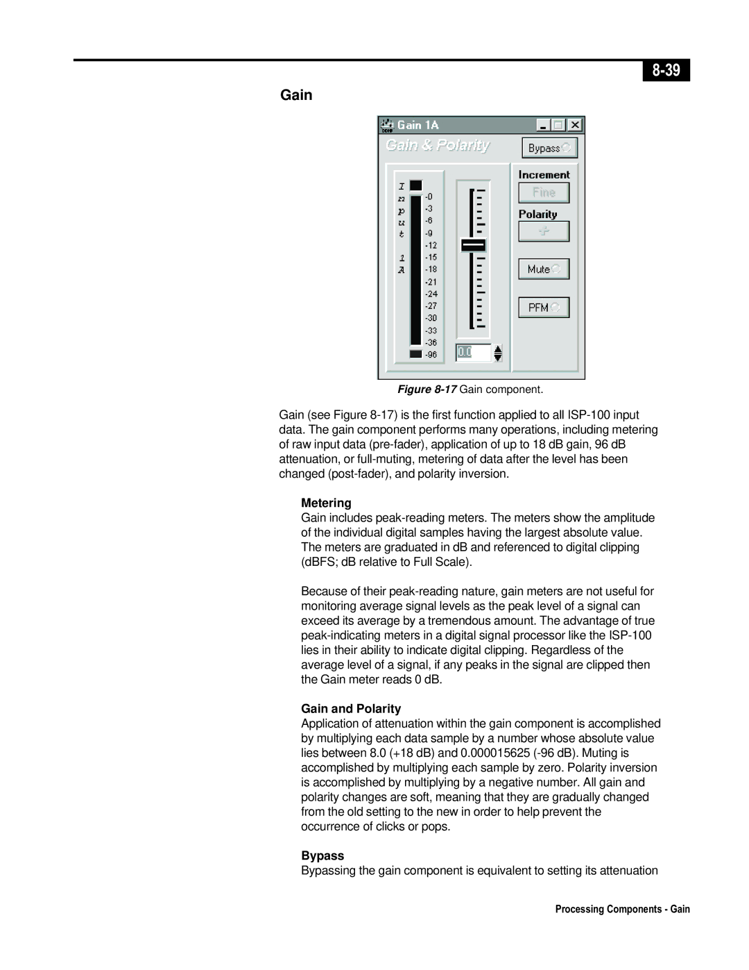
Figure 8-17Gain component.
Gain (see Figure 8-17) is the first function applied to all ISP-100 input data. The gain component performs many operations, including metering of raw input data (pre-fader), application of up to 18 dB gain, 96 dB attenuation, or full-muting, metering of data after the level has been changed (post-fader), and polarity inversion.
Metering
Gain includes peak-reading meters. The meters show the amplitude of the individual digital samples having the largest absolute value. The meters are graduated in dB and referenced to digital clipping (dBFS; dB relative to Full Scale).
Because of their peak-reading nature, gain meters are not useful for monitoring average signal levels as the peak level of a signal can exceed its average by a tremendous amount. The advantage of true peak-indicating meters in a digital signal processor like the ISP-100 lies in their ability to indicate digital clipping. Regardless of the average level of a signal, if any peaks in the signal are clipped then the Gain meter reads 0 dB.
Gain and Polarity
Application of attenuation within the gain component is accomplished by multiplying each data sample by a number whose absolute value lies between 8.0 (+18 dB) and 0.000015625 (-96 dB). Muting is accomplished by multiplying each sample by zero. Polarity inversion is accomplished by multiplying by a negative number. All gain and polarity changes are soft, meaning that they are gradually changed from the old setting to the new in order to help prevent the occurrence of clicks or pops.
Bypass
Bypassing the gain component is equivalent to setting its attenuation
Processing Components - Gain

