Save the shipping carton in case the ISP-100 needs to be returned for service.
2-1
SETUP & INSTALLATION
Introduction
This section details the setup and installation of the MERLIN ISP-100. Information is provided on the following: front and rear panel features, physical requirements, installation of expansion cards, signal connections for audio, data, and control.
Unpacking
The shipping carton is specially designed to protect the ISP-100 while transporting under normal conditions. It is still possible for damage to occur. Therefore, carefully inspect the outside carton for signs of abuse. If for any reason the ISP-100 should need to be returned, use the shipping carton that it came in. TELEX Communications, Inc. cannot warranty against damage that occurs as a result of improper packaging.
The shipping box should contain the following items:
ISP-100
User’s Manual
VUE-IT Software Package
Spare Fuses (2)
Label Paper
IEC Power Cord
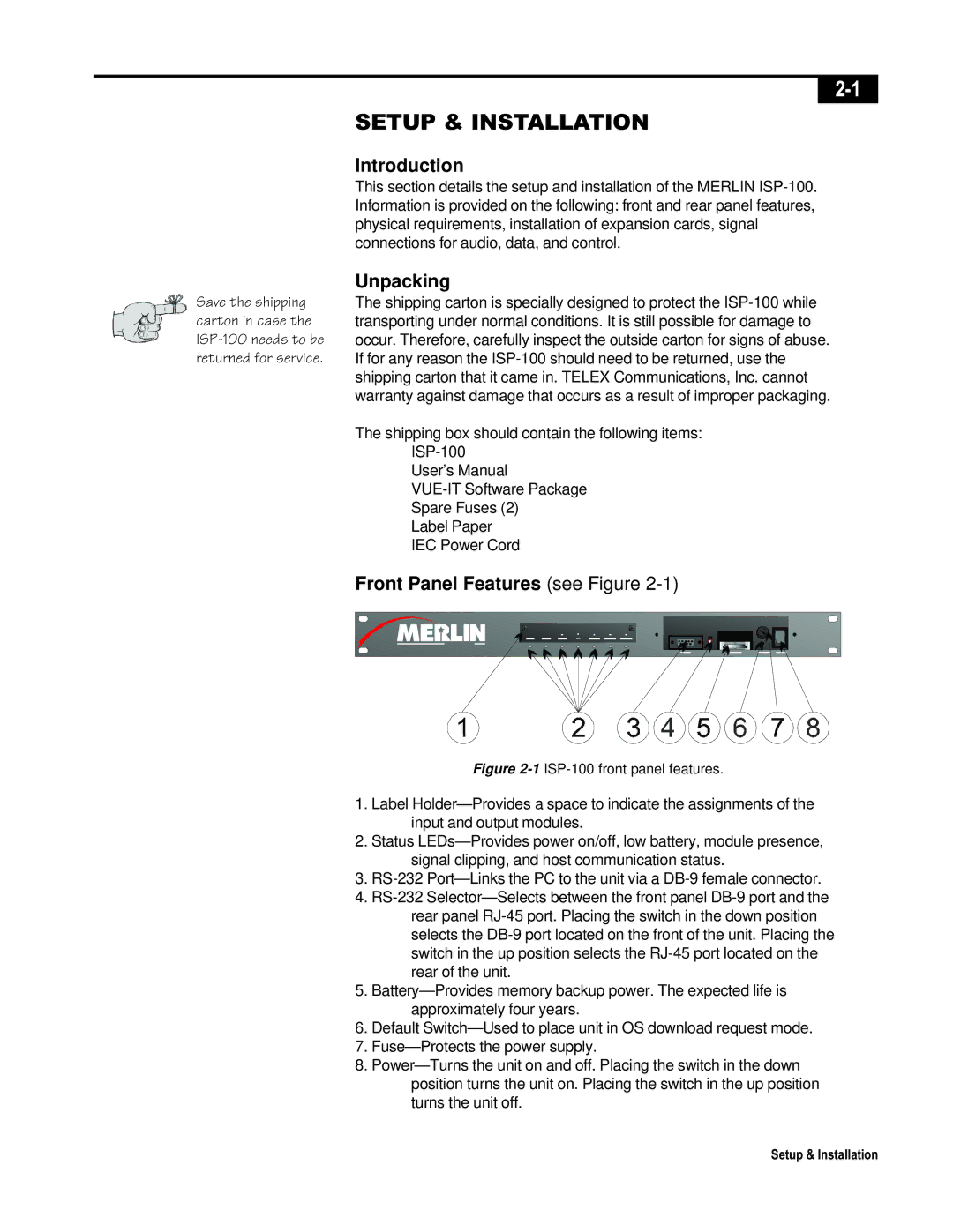
Front Panel Features (see Figure 2-1)
Figure 2-1ISP-100 front panel features.
1.Label Holder—Provides a space to indicate the assignments of the input and output modules.
2.Status LEDs—Provides power on/off, low battery, module presence, signal clipping, and host communication status.
3.RS-232 Port—Links the PC to the unit via a DB-9 female connector.
4.RS-232 Selector—Selects between the front panel DB-9 port and the rear panel RJ-45 port. Placing the switch in the down position selects the DB-9 port located on the front of the unit. Placing the switch in the up position selects the RJ-45 port located on the rear of the unit.
5.Battery—Provides memory backup power. The expected life is approximately four years.
6.Default Switch—Used to place unit in OS download request mode.
7.Fuse—Protects the power supply.
8.Power—Turns the unit on and off. Placing the switch in the down position turns the unit on. Placing the switch in the up position turns the unit off.