Use the white block on the I/O module panels to write a reference number or other designator on by using a permanent marker. Then make identical labels for the cables that plug into the module.
Long unbalanced cable runs (analog or digital) are not recommended.
Balanced Output to Unbalanced Input
Connect the “hot” wire to pin 2 of the
Digital Audio (MDM-1 Cards)
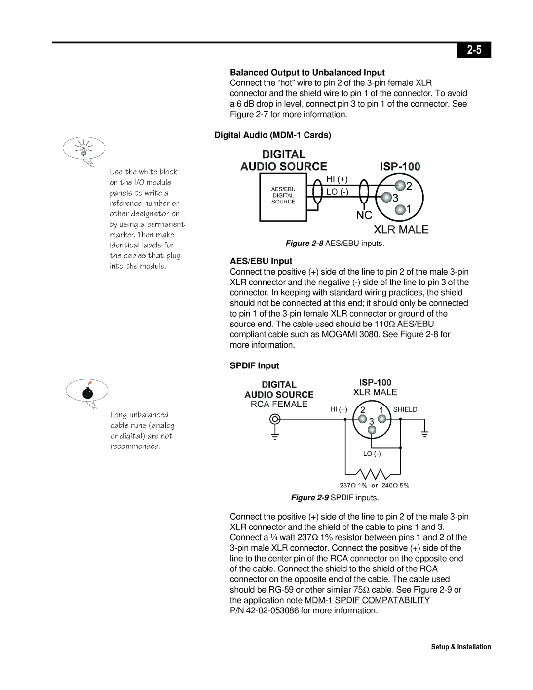
Figure 2-8 AES/EBU inputs.
AES/EBU Input
Connect the positive (+) side of the line to pin 2 of the male
SPDIF Input
Figure 2-9 SPDIF inputs.
Connect the positive (+) side of the line to pin 2 of the male
P/N
Setup & Installation
