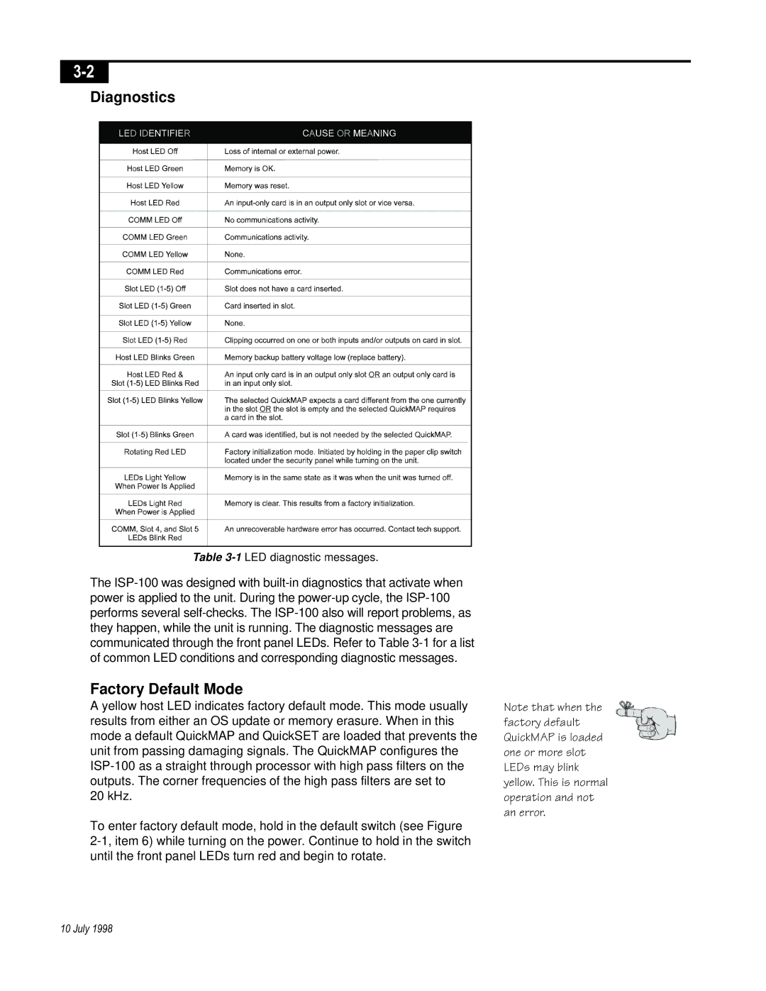
3-2
10 July 1998

Diagnostics

Table 3-1
LED diagnostic messages.
The ISP-100 was designed with built-in diagnostics that activate when
power is applied to the unit. During the power-up cycle, the ISP-100
performs several self-checks. The ISP-100 also will report problems, as
they happen, while the unit is running. The diagnostic messages are
communicated through the front panel LEDs. Refer to Table 3-1 for a list
of common LED conditions and corresponding diagnostic messages.

Factory Default Mode

A yellow host LED indicates factory default mode. This mode usually
results from either an OS update or memory erasure. When in this
mode a default QuickMAP and QuickSET are loaded that prevents the
unit from passing damaging signals. The QuickMAP configures the
ISP-100 as a straight through processor with high pass filters on the
outputs. The corner frequencies of the high pass filters are set to
20 kHz.
To enter factory default mode, hold in the default switch (see Figure
2-1, item 6) while turning on the power. Continue to hold in the switch
until the front panel LEDs turn red and begin to rotate.
Note that when the
factory default
QuickMAP is loaded
one or more slot
LEDs may blink
yellow. This is normal
operation and not
an error.