able to access
Properties for the ISP-100
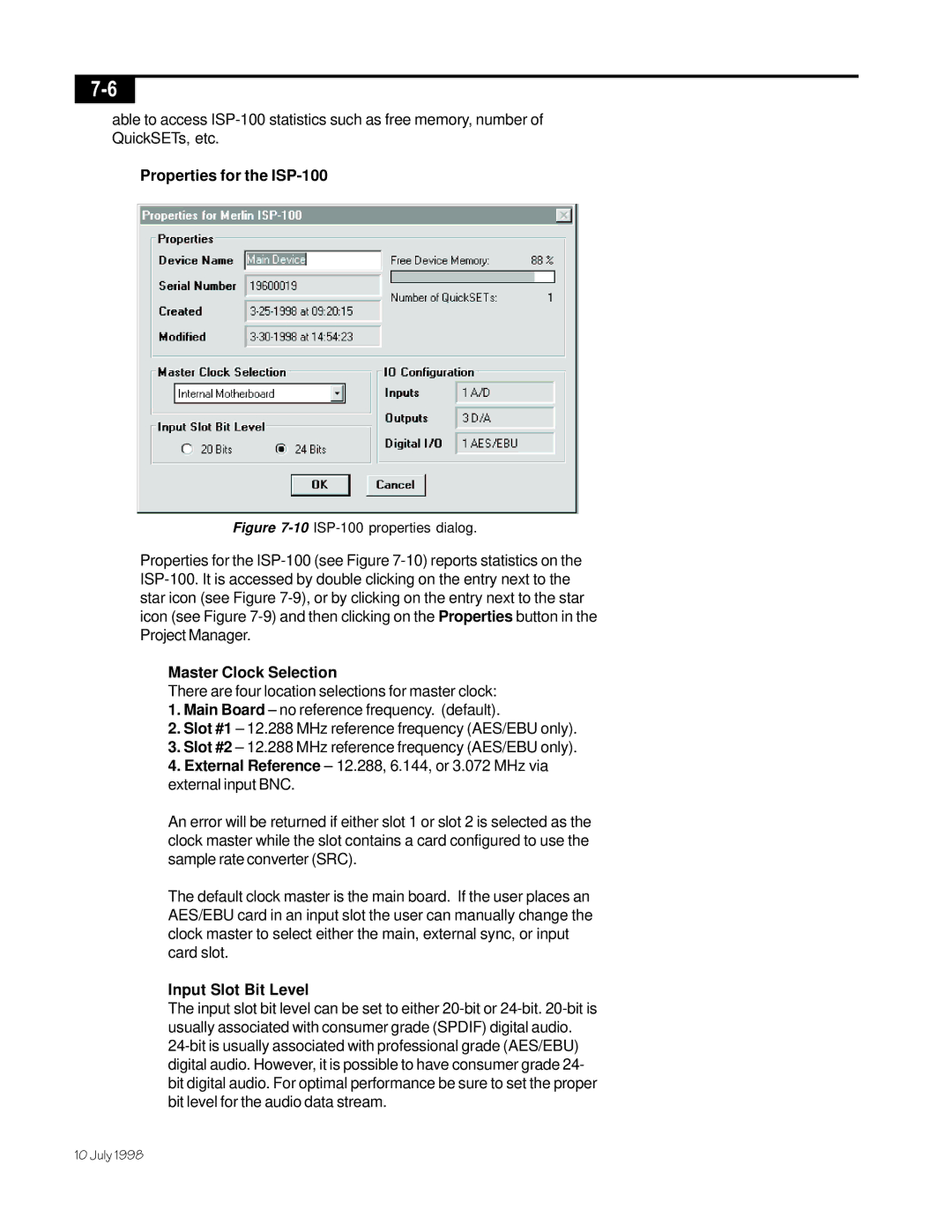
Figure 7-10 ISP-100 properties dialog.
Properties for the
Master Clock Selection
There are four location selections for master clock:
1.Main Board – no reference frequency. (default).
2.Slot #1 – 12.288 MHz reference frequency (AES/EBU only).
3.Slot #2 – 12.288 MHz reference frequency (AES/EBU only).
4.External Reference – 12.288, 6.144, or 3.072 MHz via external input BNC.
An error will be returned if either slot 1 or slot 2 is selected as the clock master while the slot contains a card configured to use the sample rate converter (SRC).
The default clock master is the main board. If the user places an AES/EBU card in an input slot the user can manually change the clock master to select either the main, external sync, or input card slot.
Input Slot Bit Level
The input slot bit level can be set to either
10 July 1998