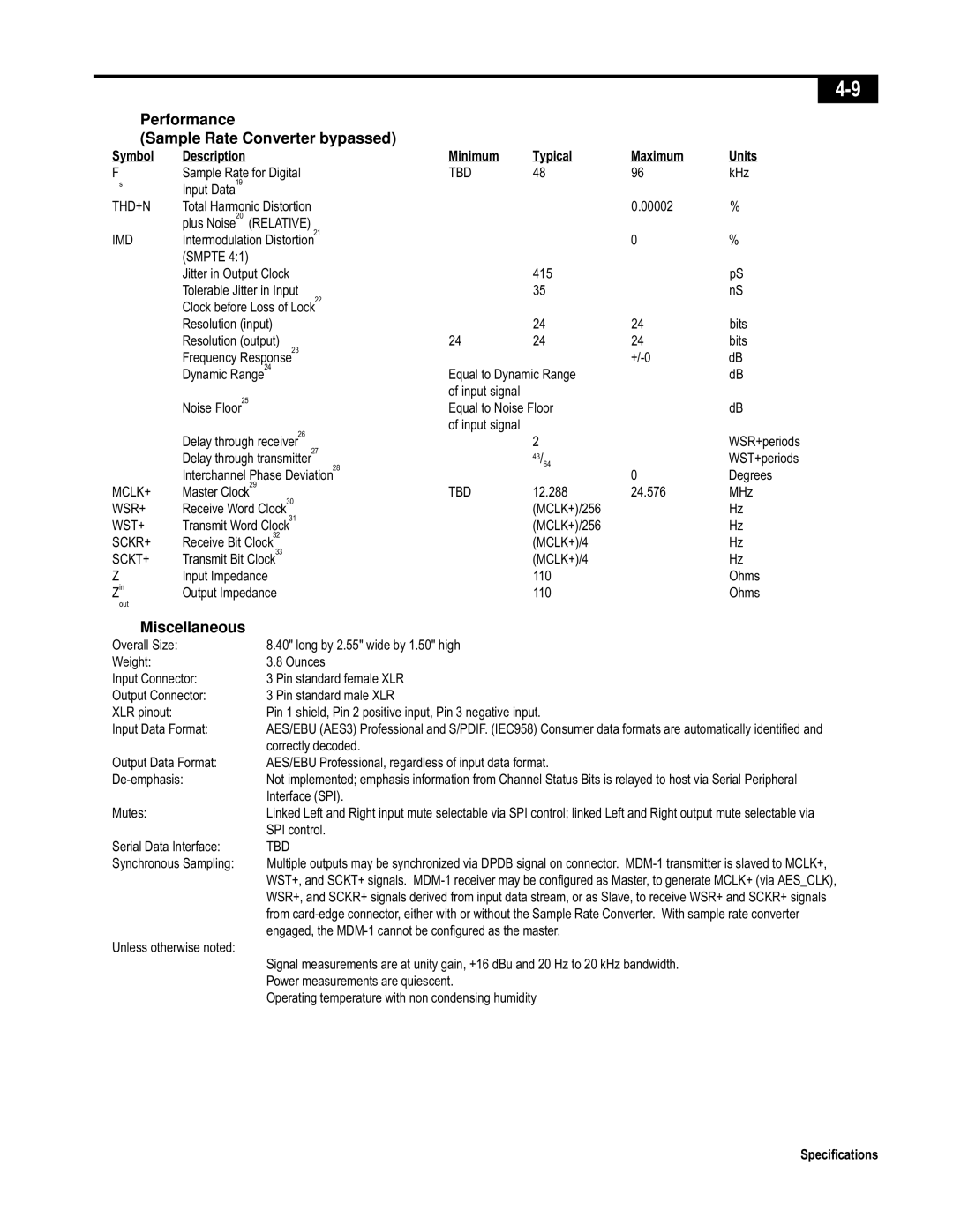
Performance
(Sample Rate Converter bypassed)
Symbol | Description | Minimum | Typical | Maximum | Units |
F | Sample Rate for Digital | TBD | 48 | 96 | kHz |
sInput Data19
THD+N | Total Harmonic Distortion |
|
| 0.00002 | % |
| plus Noise20 (RELATIVE) |
|
|
|
|
IMD | Intermodulation Distortion21 |
|
| 0 | % |
| (SMPTE 4:1) |
|
|
|
|
| Jitter in Output Clock |
| 415 |
| pS |
| Tolerable Jitter in Input |
| 35 |
| nS |
| Clock before Loss of Lock22 |
|
|
|
|
| Resolution (input) |
| 24 | 24 | bits |
| Resolution (output) | 24 | 24 | 24 | bits |
| Frequency Response23 |
|
| dB | |
| Dynamic Range24 | Equal to Dynamic Range |
| dB | |
| Noise Floor25 | of input signal |
|
|
|
| Equal to Noise Floor |
| dB | ||
| Delay through receiver26 | of input signal |
|
|
|
|
| 2 |
| WSR+periods | |
| Delay through transmitter27 |
| 43/ |
| WST+periods |
| Interchannel Phase Deviation28 |
| 64 | 0 | Degrees |
|
|
| |||
MCLK+ | Master Clock29 | TBD | 12.288 | 24.576 | MHz |
WSR+ | Receive Word Clock30 |
| (MCLK+)/256 |
| Hz |
WST+ | Transmit Word Clock31 |
| (MCLK+)/256 |
| Hz |
SCKR+ | Receive Bit Clock32 |
| (MCLK+)/4 |
| Hz |
SCKT+ | Transmit Bit Clock33 |
| (MCLK+)/4 |
| Hz |
Z | Input Impedance |
| 110 |
| Ohms |
Zin | Output Impedance |
| 110 |
| Ohms |
out |
|
|
|
|
|
Miscellaneous
Overall Size: | 8.40" long by 2.55" wide by 1.50" high |
Weight: | 3.8 Ounces |
Input Connector: | 3 Pin standard female XLR |
Output Connector: | 3 Pin standard male XLR |
XLR pinout: | Pin 1 shield, Pin 2 positive input, Pin 3 negative input. |
Input Data Format: | AES/EBU (AES3) Professional and S/PDIF. (IEC958) Consumer data formats are automatically identified and |
| correctly decoded. |
Output Data Format: | AES/EBU Professional, regardless of input data format. |
Not implemented; emphasis information from Channel Status Bits is relayed to host via Serial Peripheral | |
| Interface (SPI). |
Mutes: | Linked Left and Right input mute selectable via SPI control; linked Left and Right output mute selectable via |
| SPI control. |
Serial Data Interface: | TBD |
Synchronous Sampling: | Multiple outputs may be synchronized via DPDB signal on connector. |
| WST+, and SCKT+ signals. |
| WSR+, and SCKR+ signals derived from input data stream, or as Slave, to receive WSR+ and SCKR+ signals |
| from |
| engaged, the |
Unless otherwise noted: |
|
| Signal measurements are at unity gain, +16 dBu and 20 Hz to 20 kHz bandwidth. |
| Power measurements are quiescent. |
| Operating temperature with non condensing humidity |
Specifications
