2-4
10 July 1998

Cable Diagrams

Analog Audio (MIM-1, MIM-2, MOM-1)
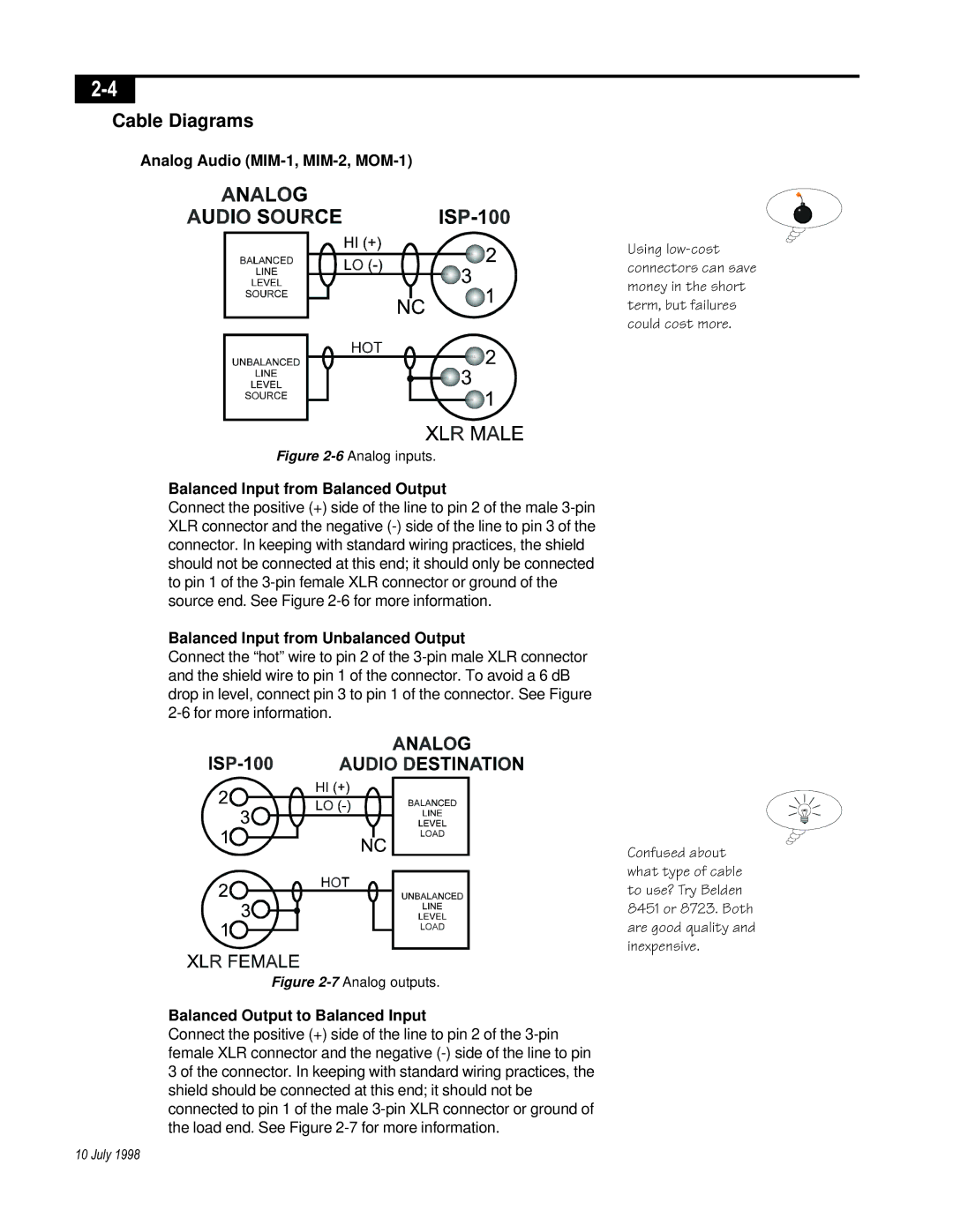
Figure 2-6
Analog inputs.
Balanced Input from Balanced Output
Connect the positive (+) side of the line to pin 2 of the male 3-pin
XLR connector and the negative (-) side of the line to pin 3 of the
connector. In keeping with standard wiring practices, the shield
should not be connected at this end; it should only be connected
to pin 1 of the 3-pin female XLR connector or ground of the
source end. See Figure 2-6 for more information.
Balanced Input from Unbalanced Output
Connect the “hot” wire to pin 2 of the 3-pin male XLR connector
and the shield wire to pin 1 of the connector. To avoid a 6 dB
drop in level, connect pin 3 to pin 1 of the connector. See Figure
2-6 for more information.
Figure 2-7
Analog outputs.
Balanced Output to Balanced Input
Connect the positive (+) side of the line to pin 2 of the 3-pin
female XLR connector and the negative (-) side of the line to pin
3 of the connector. In keeping with standard wiring practices, the
shield should be connected at this end; it should not be
connected to pin 1 of the male 3-pin XLR connector or ground of
the load end. See Figure 2-7 for more information.
Using low-cost
connectors can save
money in the short
term, but failures
could cost more.
Confused about
what type of cable
to use? Try Belden
8451 or 8723. Both
are good quality and
inexpensive.