Card Installation Procedure
CAUTION: Failure to observe
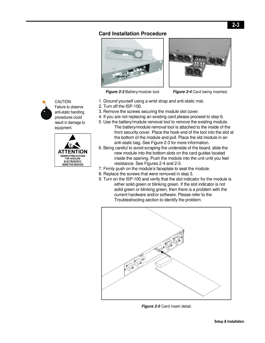
Figure | Figure |
1.Ground yourself using a wrist strap and
2.Turn off the
3.Remove the screws securing the module slot cover.
4.If you are not replacing an existing card please proceed to step 6.
5.Use the battery/module removal tool to remove the existing module. The battery/module removal tool is attached to the inside of the front security cover. Place the hook end of the tool into the slot at the bottom of the module and pull. Place the old module in an
6.Being careful to avoid scraping the underside of the board, slide the new module into the bottom slots on the card guides located inside the opening. Push the module into the unit until you feel resistance. See Figures
7.Firmly push on the module’s faceplate to seat the module.
8.Replace the screws that were removed in step 3.
9.Turn on the