1 Hardware Overview
Figures |
|
|
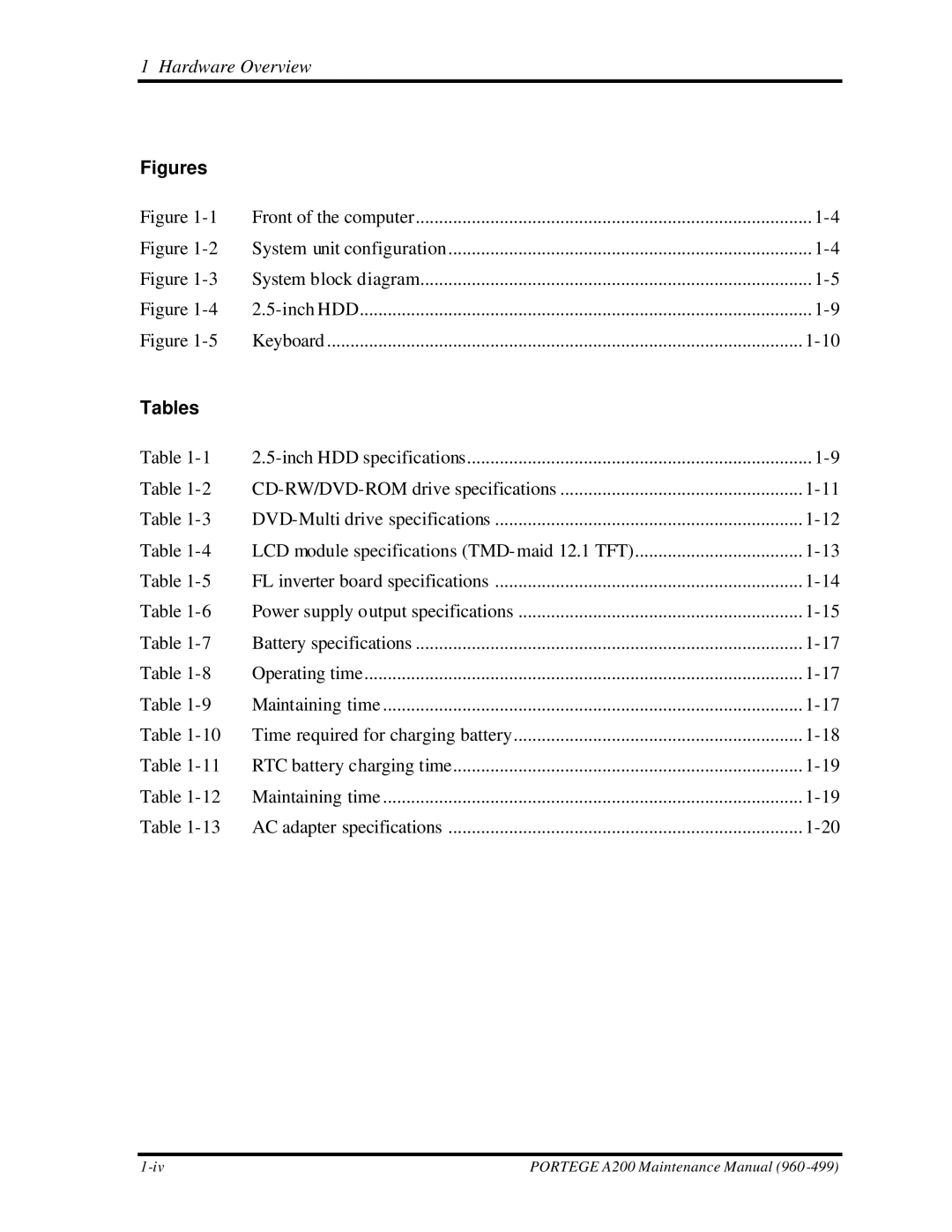
Figure | Front of the computer | |
Figure | System unit configuration | |
Figure | System block diagram | |
Figure | ||
Figure | Keyboard | |
Tables |
|
|
Table | ||
Table | ||
Table | ||
Table | LCD module specifications (TMD- maid 12.1 TFT) | |
Table | FL inverter board specifications | |
Table | Power supply output specifications | |
Table | Battery specifications | |
Table | Operating time | |
Table | Maintaining time | |
Table | Time required for charging battery | |
Table | RTC battery charging time | |
Table | Maintaining time | |
Table | AC adapter specifications |
PORTEGE A200 Maintenance Manual (960 |
