4 Replacement Procedures
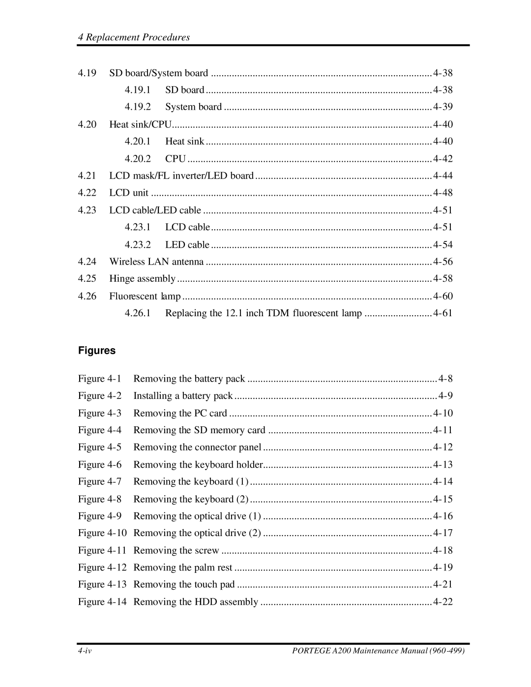
4.19 | SD board/System board | |||
| 4.19.1 | SD board | ||
| 4.19.2 | System board | ||
4.20 | Heat sink/CPU | |||
| 4.20.1 | Heat sink | ||
| 4.20.2 | CPU | ||
4.21 | LCD mask/FL inverter/LED board | |||
4.22 | LCD unit | ............................................................................................................ | ||
4.23 | LCD cable/LED cable | |||
| 4.23.1 | LCD cable | ||
| 4.23.2 | LED cable | ||
4.24 | Wireless LAN antenna | |||
4.25 | Hinge assembly | |||
4.26 | Fluorescent lamp | |||
| 4.26.1 | Replacing the 12.1 inch TDM fluorescent lamp | ||
Figures |
|
|
| |
Figure | Removing the battery pack | |||
Figure | Installing a battery pack | |||
Figure | Removing the PC card | |||
Figure | Removing the SD memory card | |||
Figure | Removing the connector panel | |||
Figure | Removing the keyboard holder | |||
Figure | Removing the keyboard (1) | |||
Figure | Removing the keyboard (2) | |||
Figure | Removing the optical drive (1) | |||
Figure | Removing the optical drive (2) | |||
Figure | Removing the screw | |||
Figure | Removing the palm rest | |||
Figure | Removing the touch pad | |||
Figure | Removing the HDD assembly | |||
PORTEGE A200 Maintenance Manual (960 |
