4.15 Cover assembly | 4 Replacement Procedures |
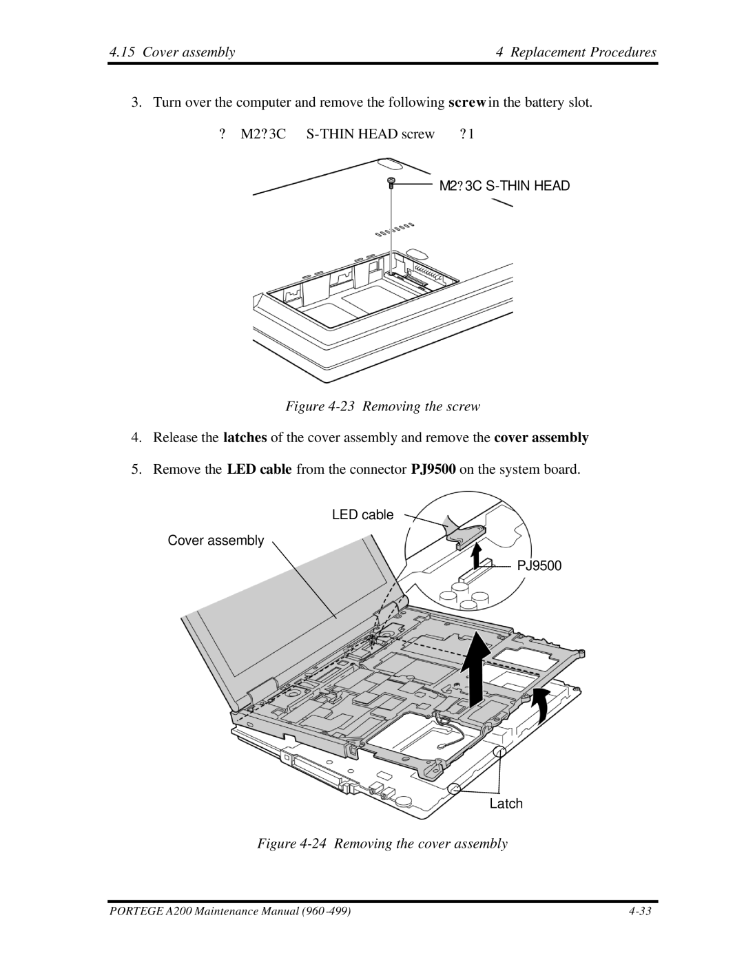
3. Turn over the computer and remove the following screw in the battery slot. | |
? M2? 3C | ? 1 |
M2? 3C
Figure 4-23 Removing the screw
4.Release the latches of the cover assembly and remove the cover assembly
5.Remove the LED cable from the connector PJ9500 on the system board.
LED cable
Cover assembly
PJ9500
Latch
Figure 4-24 Removing the cover assembly
PORTEGE A200 Maintenance Manual (960 |
