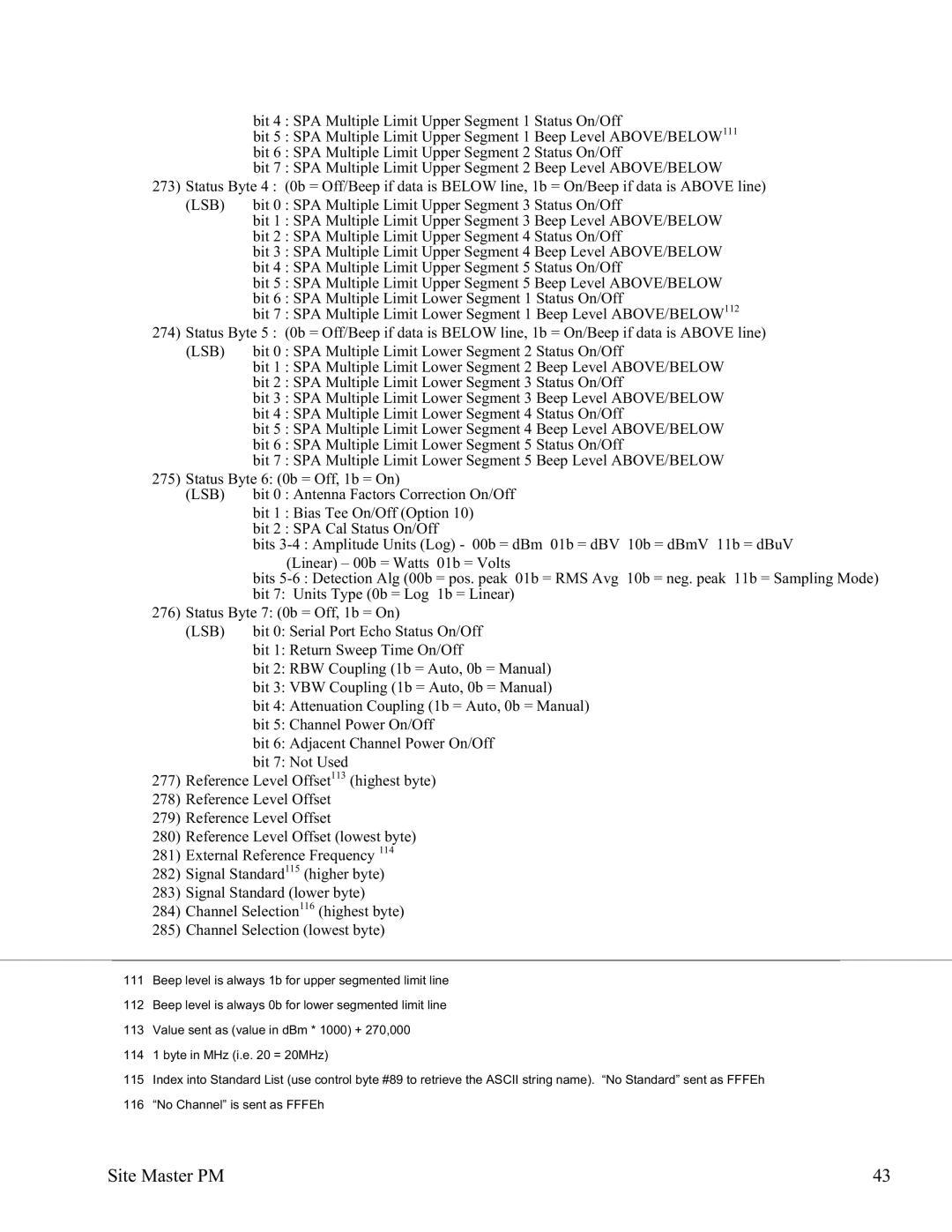
bit 4 : SPA Multiple Limit Upper Segment 1 Status On/Off
bit 5 : SPA Multiple Limit Upper Segment 1 Beep Level ABOVE/BELOW111
bit 6 : SPA Multiple Limit Upper Segment 2 Status On/Off
bit 7 : SPA Multiple Limit Upper Segment 2 Beep Level ABOVE/BELOW 273) Status Byte 4 : (0b = Off/Beep if data is BELOW line, 1b = On/Beep if data is ABOVE line)
(LSB) | bit 0 : SPA Multiple Limit Upper Segment 3 Status On/Off |
| bit 1 : SPA Multiple Limit Upper Segment 3 Beep Level ABOVE/BELOW |
| bit 2 : SPA Multiple Limit Upper Segment 4 Status On/Off |
| bit 3 : SPA Multiple Limit Upper Segment 4 Beep Level ABOVE/BELOW |
| bit 4 : SPA Multiple Limit Upper Segment 5 Status On/Off |
| bit 5 : SPA Multiple Limit Upper Segment 5 Beep Level ABOVE/BELOW |
| bit 6 : SPA Multiple Limit Lower Segment 1 Status On/Off |
| bit 7 : SPA Multiple Limit Lower Segment 1 Beep Level ABOVE/BELOW112 |
274) Status Byte 5 : (0b = Off/Beep if data is BELOW line, 1b = On/Beep if data is ABOVE line) | |
(LSB) | bit 0 : SPA Multiple Limit Lower Segment 2 Status On/Off |
| bit 1 : SPA Multiple Limit Lower Segment 2 Beep Level ABOVE/BELOW |
| bit 2 : SPA Multiple Limit Lower Segment 3 Status On/Off |
| bit 3 : SPA Multiple Limit Lower Segment 3 Beep Level ABOVE/BELOW |
| bit 4 : SPA Multiple Limit Lower Segment 4 Status On/Off |
| bit 5 : SPA Multiple Limit Lower Segment 4 Beep Level ABOVE/BELOW |
| bit 6 : SPA Multiple Limit Lower Segment 5 Status On/Off |
| bit 7 : SPA Multiple Limit Lower Segment 5 Beep Level ABOVE/BELOW |
275) Status Byte 6: (0b = Off, 1b = On) | |
(LSB) | bit 0 : Antenna Factors Correction On/Off |
| bit 1 : Bias Tee On/Off (Option 10) |
| bit 2 : SPA Cal Status On/Off |
| bits |
| (Linear) – 00b = Watts 01b = Volts |
| bits |
| bit 7: Units Type (0b = Log 1b = Linear) |
276) Status Byte 7: (0b = Off, 1b = On) | |
(LSB) | bit 0: Serial Port Echo Status On/Off |
| bit 1: Return Sweep Time On/Off |
| bit 2: RBW Coupling (1b = Auto, 0b = Manual) |
| bit 3: VBW Coupling (1b = Auto, 0b = Manual) |
| bit 4: Attenuation Coupling (1b = Auto, 0b = Manual) |
| bit 5: Channel Power On/Off |
| bit 6: Adjacent Channel Power On/Off |
bit 7: Not Used
277)Reference Level Offset113 (highest byte)
278)Reference Level Offset
279)Reference Level Offset
280)Reference Level Offset (lowest byte)
281)External Reference Frequency 114
282)Signal Standard115 (higher byte)
283)Signal Standard (lower byte)
284)Channel Selection116 (highest byte)
285)Channel Selection (lowest byte)
111Beep level is always 1b for upper segmented limit line
112Beep level is always 0b for lower segmented limit line
113Value sent as (value in dBm * 1000) + 270,000
1141 byte in MHz (i.e. 20 = 20MHz)
115Index into Standard List (use control byte #89 to retrieve the ASCII string name). “No Standard” sent as FFFEh
116“No Channel” is sent as FFFEh
Site Master PM | 43 |
