Planning Connectivity
Cables for Modems
Cables for Modems
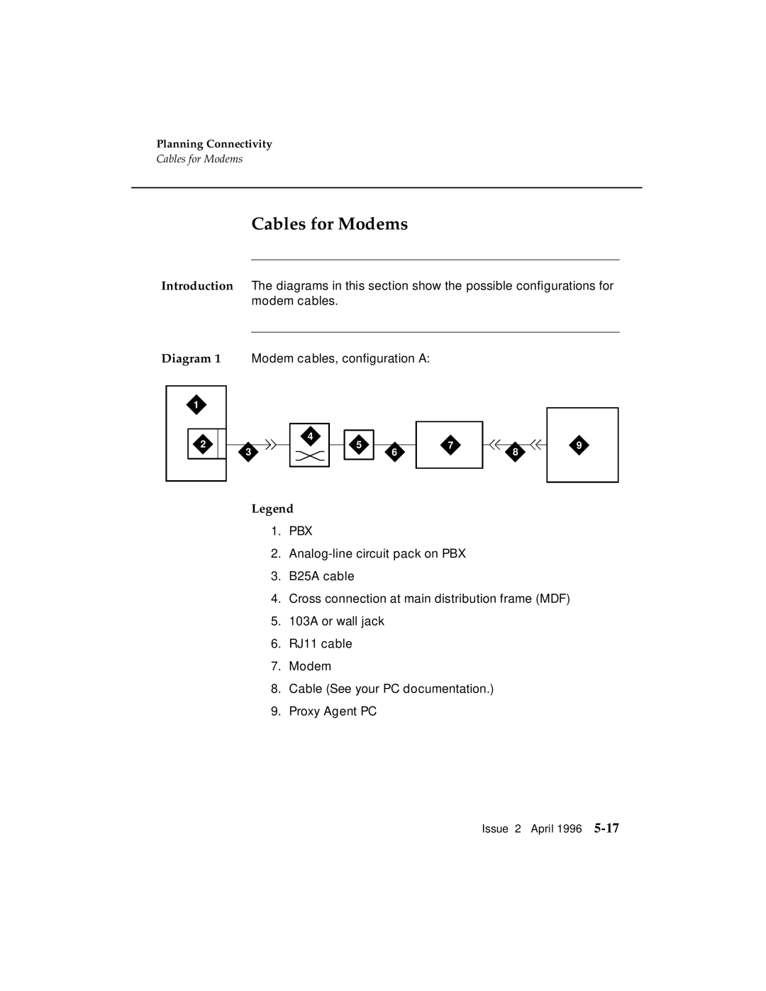
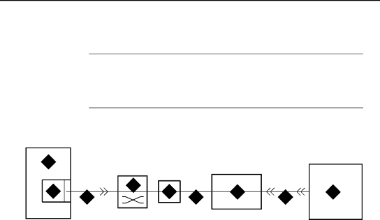
Introduction The diagrams in this section show the possible configurations for modem cables.
Diagram 1 Modem cables, configuration A:
1
|
|
|
| 4 |
|
|
|
|
|
|
|
|
|
2 |
|
|
|
| 5 |
| 7 |
|
|
|
| 9 | |
|
|
|
|
|
|
|
|
|
| ||||
3 |
|
|
| 6 | 8 |
| |||||||
|
|
|
|
|
|
|
|
| |||||
|
|
|
|
|
|
|
|
|
|
|
|
|
|
|
|
|
|
|
|
|
|
|
|
|
|
|
|
Legend
1.PBX
2.
3.B25A cable
4.Cross connection at main distribution frame (MDF)
5.103A or wall jack
6.RJ11 cable
7.Modem
8.Cable (See your PC documentation.)
9.Proxy Agent PC
Issue 2 April 1996