APPENDIX C: Cable Pinouts
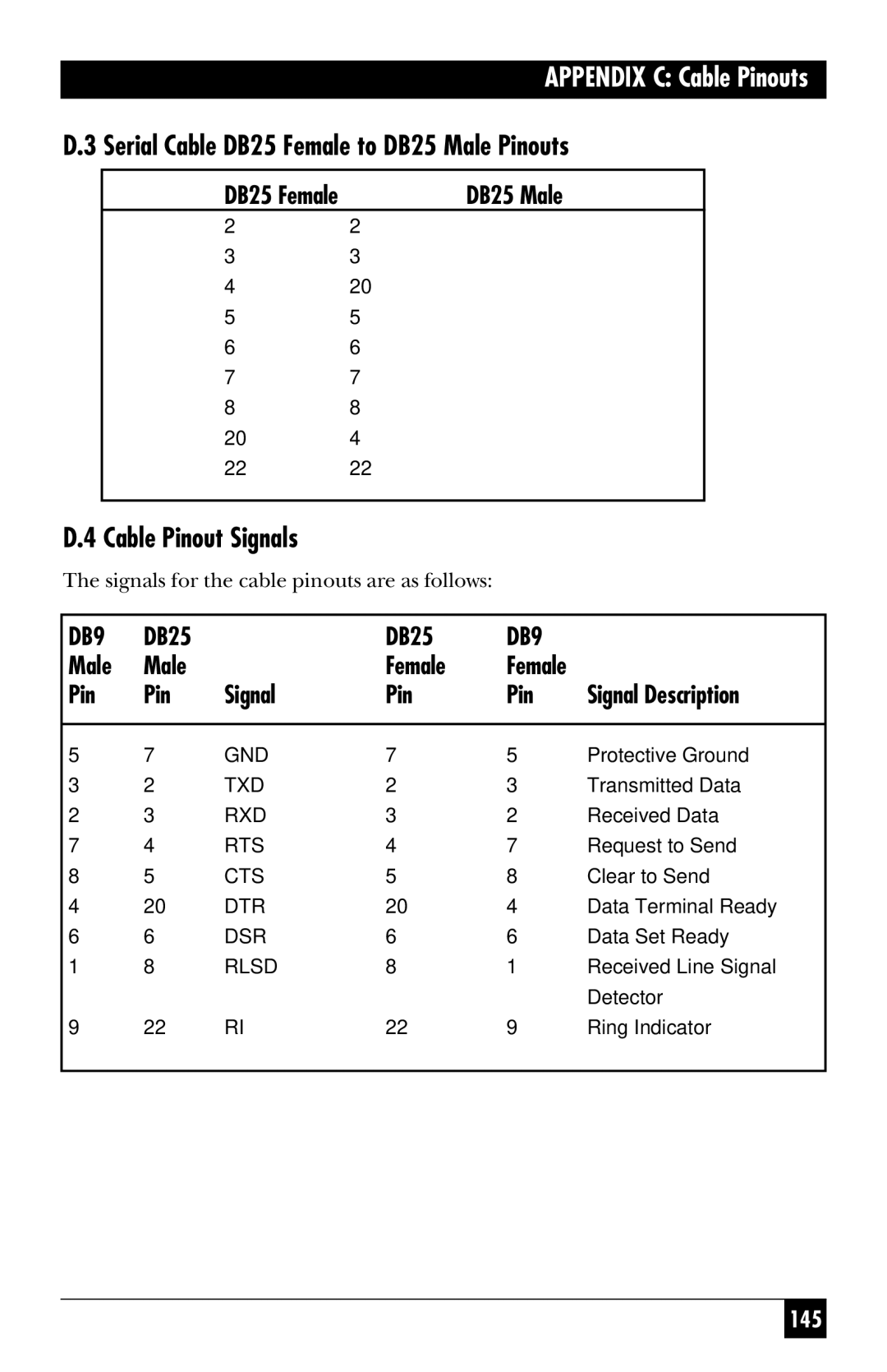
D.3 Serial Cable DB25 Female to DB25 Male Pinouts
DB25 Female | DB25 Male |
2— — — — — — — — 2
3— — — — — — — — 3
4— — — — — — — — 20
5— — — — — — — — 5
6— — — — — — — — 6
7— — — — — — — — 7
8— — — — — — — — 8
20— — — — — — — — 4
22— — — — — — — — 22
D.4 Cable Pinout Signals
The signals for the cable pinouts are as follows:
DB9 | DB25 |
| DB25 | DB9 |
|
Male | Male |
| Female | Female |
|
Pin | Pin | Signal | Pin | Pin | Signal Description |
|
|
|
|
|
|
5 | 7 | GND | 7 | 5 | Protective Ground |
3 | 2 | TXD | 2 | 3 | Transmitted Data |
2 | 3 | RXD | 3 | 2 | Received Data |
7 | 4 | RTS | 4 | 7 | Request to Send |
8 | 5 | CTS | 5 | 8 | Clear to Send |
4 | 20 | DTR | 20 | 4 | Data Terminal Ready |
6 | 6 | DSR | 6 | 6 | Data Set Ready |
1 | 8 | RLSD | 8 | 1 | Received Line Signal |
|
|
|
|
| Detector |
9 | 22 | RI | 22 | 9 | Ring Indicator |
|
|
|
|
|
|
145
