Enhanced Ethernet PLC-5 Programmable Controllers
Important User Information
Summary of Changes
Additional Ethernet PLC-5 Controller Enhancement
Is on
Publication 1785-UM012D-EN-P July
Summary of Changes
Table of Contents
Memory
Chapter Communicating with
Controller-Resident I/O
Chapter
Communicating with Devices on a DH+ Link Chapter
Communicating with a PLC-5 Adapter Channel
Extended-Local I/O
Communicating with Devices on a Serial Link
Protecting Your Programs
Preparing Fault Routines
Appendix a System Specifications
Appendix B Processor Status File
Appendix C
Appendix D
Appendix E Switch Setting Reference
Appendix F Troubleshooting
Appendix G Cable Reference
Index
Related PLC-5 Documentation
Publication Title Publication Number
Term Definition
Controllers in this manual only
Manual Overview
This manual has three main sections Design Operate Maintain
Preface Publication 1785-UM012D-EN-P July
Extended-local I/O scanner
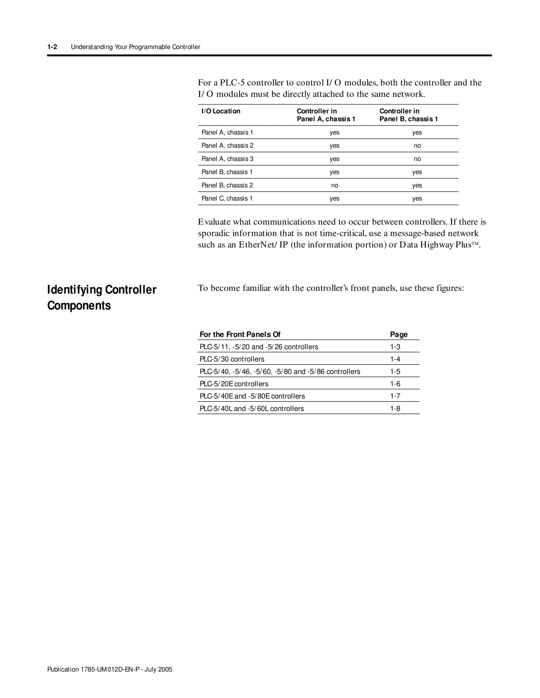
Using This Chapter Lay Out the System
For Information About
PLC-5/11, -5/20 and -5/26 controllers PLC-5/30 controllers
Identifying Controller Components
For the Front Panels
No parity
Keyswitch selects controller mode
Install memory module here Install battery here
Keyswitch selects controler mode
PLC-5/30 Controller Front Panell
4Understanding Your Programmable Controller
DF1 point-to-point One stop-bit 2400 bps
Install memory module here PLC-5 family member designation
Channel 2B status indicator lights green and red
Channel 1B status indicator lights green and red
External transceiver fuse Keyswitch selects controller mode
Configure this 3-pin port for
PLC-5/20E Controller Front Panel
6Understanding Your Programmable Controller
PLC-5/40E and -5/80E Controller Front Panels
8Understanding Your Programmable Controller
Install battery here PLC-5 family member designation
PLC-5/40L and -5/60L Controller Front Panels
If You Want to
This Capability Lets You
MCP
PLC-5/40
1771-ASB Remote I/O Link Cable Belden
Scanner-mode PLC-5 controller
At housekeeping
Connect the controllers via the remote I/O link
Controller transfers I/O data and status data using
12Understanding Your Programmable Controller
Publication 1785-UM012D-EN-P July
Scanner
14Understanding Your Programmable Controller
Using This Chapter
Selecting and Placing I/O
Selecting I/O Modules
Selecting I/O modules
Selecting I/O Module Density
Choose this Type
Explanation
Module Examples
Selecting and Placing I/O
Input Output
4Selecting and Placing I/O Publication 1785-UM012D-EN-P July
Placing System Hardware
Acceptable Range
51mm Wiring Duct 102mm 153mm
2Placing System Hardware
102mm 51mm2
Mount the I/O chassis horizontally
Troubleshooting is convenient
Preventing Electrostatic Discharge
Protecting Your Controller
RFI, we recommend a steel enclosure
Laying Out Your Cable Raceway
Categorize Conductors
Route Conductors
4Placing System Hardware
Side
Chassis Dimensions Series B
Laying Out Your Backpanel Spacing
Chassis and External Power Supply Dimensions
6Placing System Hardware
Ground Bus To Grounding Electrode System
Recommended Grounding Configuration for Remote I/O Systems
Enclosure
8Placing System Hardware Publication 1785-UM012D-EN-P July
Addressing I/O and Controller Memory
Classification Term Relation to Controller Memory
Addressing as It Relates to an I/O Terminal
2Addressing I/O and Controller Memory
Choosing an Addressing Mode
16-point Example
Input
Termi
Nals
Point Example
Point input module
Controller memory Rack
Group Point input module Point output module Word #
Example of Efficient I/O Image Table Use
6Addressing I/O and Controller Memory
Addressing Mode Guidelines
Addressing Summary
Addressing Block-Transfer Modules
Use this table as a quick reference for addressing
If Using this Slot Addressing Chassis Size Results
Assigning Racks
Slot Rack Racks 2 racks
8Addressing I/O and Controller Memory
When assigning remote I/O rack numbers, use these guidelines
Controller memory is divided into two basic areas
Understanding Data Storage Data-Table Files
Specify the file in which the data is stored
Formatted address
Data, you specify it with a formatted address
12Addressing I/O and Controller Memory
Addressing File Types
1000words
Words/1000 structures Structure
14Addressing I/O and Controller Memory
Understanding Program-File Storage
Valid Data Types/Values Are
Accepts Any
Program File Number of Words Used
Valid formats for addressing data files are
Addressing
Specifying I/O Image Addresses
To Specify the Address of a Use these Parameters
Where Is
Specifying Logical Addresses
TON, TOF, RTO
Specifying Indirect Addresses
Word Level Example Bit Level
Example Variable Explanation
Specifying Indexed Addresses
Value Base Address
Source N710 N720
N115 N1115
Specifying Symbolic Addresses
LS1
AUTO1
SW1
Optimizing Instruction Execution Time and Controller Memory
22Addressing I/O and Controller Memory
Following examples illustrate these concepts
Effectively Using I/O Memory
Use Application
Configuring the system for controller-resident I/O
Introduction to PLC-5 Controller Scanning
Program Scanning
2Communicating with Controller-Resident I/O
Transferring Data to Controller-Resident I/O
Transferring Discrete Data to Controller-Resident I/O
Transferring Immediate I/O Requests
Transferring Block-Transfer Data to Controller-Resident I/O
4Communicating with Controller-Resident I/O
Communicating to a remote I/O node adapter
Configuring a controller channel as a scanner
Communicating with Remote I/O
Can Connect
Category Product Catalog Number
An example remote I/O system looks like this
Introduction to Remote I/O
Block-transfer data with remote I/O devices
Designing a Remote I/O Link
Network using a daisy chain or trunk line/drop line
Configuration
Transmission rate. Configure all devices on a remote I/O
Link to communicate at the same transmission rate
Configuring a Controller Channel as a Scanner
Catalog Number Series
Specify the scan list Publication 1785-UM012D-EN-P July
Specify Channel Configuration Information
Define an I/O Status File
Diagnostic file
Scanner mode link 57.6, 115.2, and 230.4 kbps
This Field Define By Doing the Following
Cursor to the field, type an integer file number
Specify the Scan List
Scan list includes the following
Do the Following
For this Field Scan List Contains
10Communicating with Remote I/O
Communicating to a Remote I/O Node Adapter
Remote I/O Scan and Program Scan Loops
ASB Adapter Modules, Do the Following See
Appendix E
Troubleshooting Remote I/O Communication Difficulties
12Communicating with Remote I/O
Interrupt from STI or Fault Routine
Remote I/O Scan Extended Local
Racks
Adapter used in the remote I/O scan is the 1771-ASB
Description
Block-Transfer Minor Fault Bits
Minor Fault Description
Channel pairMinor fault bits set
PLC-5 typeMaximum number of command blocks
16Communicating with Remote I/O
Packet includes data if it is a block-transfer write
Block-transfer module
Transfer read
Block-Transfer Sequence with Status Bits
Yes Does this slot address
Does the module respond?
Yes See
Sets the error .ER bit Yes
18Communicating with Remote I/O
Yes Sets the done .DN bit
Go to
General Considerations
Retries request once more before setting the .ER bit
Block-Transfer Programming Considerations
For Controller-Resident Local Racks
20Communicating with Remote I/O
Status Field Location Description
Monitoring transmission retries
Monitoring Remote I/O Scanner Channels
Fault
Reset
Field indicating the rack was globally reset
Rack Address
Error
Messages sent with error
Messages Tab Messages = SDA messages + SDN messages
Messages unable to receive
N1547
24Communicating with Remote I/O
Defined I/O status file
Fault Bits
Present Bits Fault Bits Not Used
When you use a ladder program or the software to
Inhibit and reset an I/O rack, you must set or clear
Reset and inhibit bits that correspond to each quarter
Rack in a given chassis. Failure to set all the appropriate
Configuring communication to a PLC-5 adapter channel
Communicating with a PLC-5 Adapter Channel
Monitoring remote I/O adapter channels
Monitoring the status of the supervisory controller
2Communicating with a PLC-5 Adapter Channel
Configuring Communication to a PLC-5 Adapter Channel
Into for the supervisory controller
Remote I/O Adapter
Specify adapter settings Publication 1785-UM012D-EN-P July
Controller
Default is rack
Status information
Damage can result
Cursor to the field and select the desired rate
Specify the Discrete Transfer Configuration Files
6Communicating with a PLC-5 Adapter Channel
Discrete Data and Block-Transfer Status
8Communicating with a PLC-5 Adapter Channel
Input destination
Enter the file number decimal of the source data
Enter the word number decimal of the source data
Adapter’s input file
Programming Discrete Transfers Adapter Mode
Data to an Adapter Channel
10Communicating with a PLC-5 Adapter Channel
0x7 N5115
Configure Block-Transfer Requests
12Communicating with a PLC-5 Adapter Channel
Adapter Mode Configuration screen
Data Monitor screen
BT100 Has a length of 64 words
Must Match
BT000000 BT010000 BT011000 BT011001 BT011040
Examples of Block-Transfer Ladder Logic
14Communicating with a PLC-5 Adapter Channel
PLC-5 adapter-mode processor is configured for rack
Condition the use of BTR data with a data valid bit
BR0200 BWO200
Data Not Valid Bit
Locations of module 0 and 1 data
16Communicating with a PLC-5 Adapter Channel
Word For status Output File Input File Module
Adapter channel status
Monitoring the Status of the Adapter Channel
Status bits sent to scanner
When this Bits It Indicates
Monitoring the Status of the Supervisory Controller
Adapter
Messages received with error
Monitoring Remote I/O Adapter Channels
Page
Configuring the controller as an extended-local I/O
For Information About Go to
Scanner Monitoring extended-local I/O status
PLC-5/40L and -5/60L processor
Cabling
Form a custom cable length. For example, if you have a
You cannot connect two 2 m cables together. You would
Have to use the 5 m cable and have the extra 1 m as slack
Processor-resident local I/O racks
Numbered 4, 5, 10, 11, 12,
4Communicating with Extended-Local I/O
PLC-5/40L and -5/60L I/O Scanning and Update
Transferring Data
Extended Local I/O Data Exchange Image Update
Discrete Data Transfer
Remote I/O Scan
PLC-5/40L and -5/60L Extended-Local I/O Scan Time
Transferring Block Data
6Communicating with Extended-Local I/O
This formula assumes
Calculating Block-Transfer Completion Time
Where
Considerations for Extended-local Racks
8Communicating with Extended-Local I/O
This Field Specifies Configure by Doing the Following
Scan list Channel I/O configuration
Want to get status information for that channel
List
Or 1/2-Slot
Slot Logical rack Logical racks 11/2 logical rack
Remote I/O Scan List vs Extended-local I/O Scan List
10Communicating with Extended-Local I/O
An asterisk * after a range indicates the last
Valid rack entry
Automatically calculated based upon rack
Switch settings on the adapters are set correctly
Display the new configuration when you save edits
Monitoring Extended-Local I/O Status
Screen
Channel retry Word
Retry counts
Retry Word
Word Multiples Etc Entry
Page
Using the global status flag file
Selecting Devices That You Can Connect
Selecting devices that you can connect Link design
Estimating DH+ link performance Application guidelines
Link Design
Configuring the Channel for DH+ Communication
You must set switch assembly SW1 on the controller
Serial port or a PLC-5 coprocessor, use channel 2 for
Better overall system performance
Diagnostic file File containing the channel’s
Link ID Local link where the channel
Status information Words long
Other used file. Unpredictable machine damage can result
Using the Global Status Flag File
Pass data
System creates an integer file 64 words long
Information previously in this file is lost
Octal N107 Octal N1010 Octal N1015 Octal N1030
Files are updated during housekeeping
6Communicating with Devices on a DH+ Link
Status Field Words Description
Monitoring messages
Monitoring DH+ Communication Channels
Monitoring Data Sent with Acknowledgment
Need updates once per second
Noise or a cabling problem
Transmit confirm
Transmit NAK full
Monitoring Data Sent without Acknowledgment
10Communicating with Devices on a DH+ Link
Monitoring General Status
Noise or cabling problems
Linear scan failed
Started linear scan below for more information
Token retry
Sending Command Type Maximum Packet Station Size Data Words
Nodes
Size and Number of Messages
PLC-5
Completes the message transaction Station
Message Destination
14Communicating with Devices on a DH+ Link
Internal Processing Time
Average DH+ Link Response Time Test Results
16Communicating with Devices on a DH+ Link
Number of Controllers
50 W 100 W + 250 W X 500 W =Words
Application Guidelines
Number of Controllers
Page
This Is Normally Used When You Method
Communicating with Devices on a Serial Link
Choosing Between
RS-423
Using Channel
User Mode
System Mode
10-2Communicating with Devices on a Serial Link
Use this Mode For
DF1 Master Mode
DF1 Slave Mode
Point-to-Point
Method Option Name Principal Benefits
Polling Inactive Priority Stations
Changing Modes
Follow these guidelines
Port Transmission
Configuring Channel
Configure Channel 0 for DF1 Point-to-Point
DF1 slave 10-9 DF1 master 10-12 User mode
If You Want to Use
Serial Settings
Option Settings
DF1 Enqs
Configure Channel 0 as a Slave Station
Select Enabled or Disabled
Option is enabled
To get status information for that channel
Error checking. CRC is more complete checking
Select one of the following
Driver
Station address
RTS send delay Amount of time that elapses
Signal and the beginning
RTS signal
Message ACK timeout Amount of time you want
Configure Channel 0 as a Master Station
10-12Communicating with Devices on a Serial Link
Enter a valid value RTS send delay
Octal
Retried before being declared
This time allows the modem to
Polling Settings
Master message
If you want the master station to
Transmit Message transmit
Between Station Polls
Default size is 64 words
Default size is 18 words
Remote stations
Priority poll file
Contains this Information
Being polled, etc
New remote station is polled
Word 2 through word
Configure Channel 0 for User Mode Ascii Protocol
Remote mode change
10-18Communicating with Devices on a Serial Link
File containing the channel’s
10-19
XON/XOFF
Enable
Disable
If You Want To Select
Remotely
10-22Communicating with Devices on a Serial Link
Using the System Mode Status Display
Monitoring Channel 0 Status
DCD recover
High
Messages sent
Device
Using the User Mode Ascii Status Display
Modem Lines
Communicating with Devices on an Ethernet Network
Using This Chapter Media and Cabling
Configuring channel 2 for Ethernet communication
Manually Configuring Channel
Network Addressing
Assigning Your IP Address
11-2Communicating with Devices on an Ethernet Network
11-3
Ethernet Channel 2 Configuration Fields
With programming software if Bootp is enabled
Using Bootp to Enter Configuration Information
Network This field is required when you
Broadcast Address
Controller should respond
11-6Communicating with Devices on an Ethernet Network
Editing the Bootptab Configuration File
Based on this configuration, the Bootptab file looks like
11-8Communicating with Devices on an Ethernet Network
Using Broadcast Addressing
If Bootp is enabled, you can’t change any
Advanced Ethernet communications characteristics
Broadcast addressing 11-9 Subnet masks and gateways 11-11
C.dWhere a, b, c, d are between 0-255 decimal
If you change the default and need to reset it, type
Form
11-10Communicating with Devices on an Ethernet Network
Using Subnet Masks and Gateways
Using Bootp to configure Be sure Bootp is enabled 11-13
If You are Then See
11-12
Subnet Mask Controller’s subnet mask
Subnets
Enter an address of the following form
Local subnet
Personal computer Windows
Or HP 9000 or VAX computer
Server 130.151.194.xxx Ethernet TCP/IP network
130.151.132.1
Bootptab files that correspond to this example looks like
11-14Communicating with Devices on an Ethernet Network
Using Domain Name Service
Using the Embedded Web Server
11-16Communicating with Devices on an Ethernet Network
Diagnostic Information
11-18Communicating with Devices on an Ethernet Network
This Counter Totals
This Indicates
Application Memory
Session Table Connections
11-20Communicating with Devices on an Ethernet Network
11-21
Generating User Provided Web Pages
11-22Communicating with Devices on an Ethernet Network
Output Timer
Status Counter Control
11-24Communicating with Devices on an Ethernet Network
Input image word is I0 is b!ABDTR-I0/b
Time values in T40 are!ABDTR-T40
BCD
Importing User Page Files to the PLC-5 Controller
11-26Communicating with Devices on an Ethernet Network
11-27
11-28Communicating with Devices on an Ethernet Network
11-29
Following examples use this system configuration
Multihop Examples
11-31
11-32Communicating with Devices on an Ethernet Network
Communicating with ControlLogix Devices
Comparing Multihop and Non-Multihop Messages Over Ethernet
Interpreting Error Codes
Controller sets the .ER bit and enters an error code
Code Hexadecimal Description
Displayed on the data monitor screen
Interpreting Ethernet Status Data
F00A
Active screen
11-34Communicating with Devices on an Ethernet Network
Monitoring general Ethernet status
Status Field Bytes Displays the Number
11-36Communicating with Devices on an Ethernet Network
Monitoring Ethernet commands
Monitoring Ethernet replies
Personal Computer
Ethernet PLC-5 Performance Considerations
Performance Host to Ethernet PLC-5 Controller
PLC-5 Controller Typed Write Packet Size
11-38Communicating with Devices on an Ethernet Network
Using protected controllers 12-6
Protecting Your Programs
12-4
File Assigning a privilege class to a node 12-4
Node privileges override the default privilege class
Channel
Structure
Defining Privilege Classes
Will be appropriate for a particular application
12-4Protecting Your Programs
Assigning a Privilege Class to a Node
Assigning a Privilege Class to a Channel or Offline File
12-5
Page
Programming Considerations
Forcing
Forcing Inputs and Outputs
13-11
13-2Programming Considerations
Extended Forcing
Forcing SFC Transitions
That you include in the extended force configuration
Do not use BTR data tables files to store
Non-block-transfer data. All non-block-transfer data
Table as read data will be forced to zero during
Enabled 003 ms Disabled 0015 ms
Increased Program Scan Time
Force Privileges
13-4Programming Considerations
Using Protected Controllers
Setting Up and Using Extended Forcing
With the Programming Software
Package
Select Which Group of Data You Want to Force
13-6Programming Considerations
Select all of data file N11
BTR #2 and ending at the end of BTR #4
Forces Must be of Type B, A, N, or D
Enable or Disable the Forces
Using Extended Forcing with Time-Critical Applications
Radix Force Screen Display
Binary
Enable the BTW
OTL
Using Special Programming Routines
13-10Programming Considerations
Deciding When to Use Special Routines
Priority Scheduling for Interrupts and MCPs
Program Execution States
13-12Programming Considerations
Program would be executing if it were of a higher priority
An MCP, STI, PII Does the program fault?
Rescheduling Operation
13-14Programming Considerations
I012
Program can be
Interrupted
Power-up routines Fault routines
Defining and Programming Interrupt Routines
Page
Preparing Power-Up Routines
Setting Power-Up Protection
If S26/1 is After power loss, the controller
Set
Defining a Controller Power-Up Procedure
Portion of the fault routine associated with a particular
Fault or power-up condition
Allowing or Inhibiting Startup
Use this Bit
15..............0
Page
Preparing Fault Routines
Responses to a Major Fault
Understanding the Fault Routine Concept
For Information About See
Faults
Understanding
General
It Sets
Fault in a Remote I/O Chassis
Preparing Fault Routines
15-4Preparing Fault Routines
Remote inputs inactive
Here are two programming methods you can use
Inputs
15-5
Programming a Fault Routine
Avoiding Multiple Watchdog Faults
To fault mode without completing the fault routine
If You Encounter Then
Setting an Alarm
Clearing a Major Fault
Fault. Be sure to examine the fault bit and correct
Cause of the fault before clearing it
Example of Comparing a Major Fault Code with a Reference
If the Fault Routine Then the Controller
Then faults
15-8Preparing Fault Routines
Changing the Fault Routine from Ladder Logic
Using Ladder Logic to Recover from a Fault
Ways to Recover from a Rack Fault Method Description
Monitoring Faults
Block-Transfers in Fault Routines
Testing a Fault Routine
You can Monitor Description
Monitoring Major/Minor Faults and Fault Codes
Interpreting Major Faults
Interpreting Minor Faults
For a description of the major faults S11, see Appendix B
PLC-5/60, -5/60L, -5/80, 5/80E
Monitoring Status Bits
PLC-5/11, -5/20, 5/20E PLC-5/30 PLC-5/40, -5/40L, 5/40E
Page
Selecting Main Control Programs
Using Main Control Programs
Consider Using this Technique If You are
16-2Using Main Control Programs
MCP
Configuring MCPs
An I/O update
Using Main Control Programs
If the MCP is a Following Occurs
This Field Do the Following Status File
Monitoring MCPs
Page
Writing STI Ladder Logic
Using Selectable Timed Interrupts
Using a Selectable Timed Interrupt
17-2Using Selectable Timed Interrupts
Control R60 Length Position Mode
STI Application Example
Block-Transfers in Selectable Timed Interrupts STIs
Defining a Selectable Timed Interrupt
Do the Following Status File
STI. If you disable the STI write a 0 to S31,
Monitoring Selectable Timed Interrupts
Controller uses the value in S30 to determine how often to
Check for a non-zero value in S31
Using Processor Input Interrupts
Using a Processor Input Interrupt
Using a processor input interrupt
18-1
Mode Description
Writing PII Ladder Logic
PII Application Examples
Two ways that you can use a PII program
Counter C40 Preset 100 Accum
Block-Transfers in Processor Input Interrupts PIIs
Output image bit remains set until the next count
C40.CU
18-4Using Processor Input Interrupts
Design Considerations
Defining a Controller Input Interrupt
Monitoring Controller Input Interrupts
This PII Field Stores Address
System Specifications
Controller Specifications
Memory and Channel Specifications
Controller Maximum
Maximum Maximum Number of I/O Cat. No
Any Mix
PLC-5/60 64 K2 Any mix or
Compatible PLC-5/60L 64 K2 Any mix or
Compatible Extended Local I/O PLC-5/80 100 K3 Any mix or
Compatible PLC-5/80E 100 K3 Any mix or
Battery Specifications
Eeprom Compatibility
Available
Eeprom compatibility is related to
Area Description
6System Specifications Publication 1785-UM012D-EN-P July
Processor Status File
S0 S2
This Word Stores Arithmetic flags
Step in an SFC
2Processor Status File
S2Switch setting information
This Word Stores
S3-10
S11
S12
This word stores the following fault codes
This Fault Code Indicates this Fault Fault Is
Error using SFR. This error occurs if
Non-recoverable. The fault
You jumped to an invalid non-ladder file
For instruction with missing NXT
Publication 1785-UM012D-EN-P July
8Processor Status File
Recoverable
Service
S13-S24
S26-S35
RUN
S36-S78
S79-S127
Maximizing System Performance
Using This Chapter Program Scan
Using program control instructions
Effects of Different Input States on Logic Scan Time
Effects of False Logic versus True Logic on Logic Scan Time
Other instructions may have a greater or lesser effect
If I000/00 is Then the Rung is
Effects of Using Interrupts on Logic Scan Time
Effects of Different Instructions on Logic Scan Time
Editing While in Remote Run Mode
Effects of Housekeeping Time
Online editing times for ladder programs are as follows
For this Editing Operation This Type Times are Program
Calculating Throughput
Using Global Status Flag Files
Card Backplane + Card Remote I/O Processor Delay Scan Time
6Maximizing System Performance
Input and Output Modules Delay
Remote I/O Scan Time
Communication Rate
Number of Rack Entries
Time Rate kbps
57.6 115.2 230.4
8Maximizing System Performance
Block-Transfers
Ms/Word Overhead ms Rate kbps
Kbps Rack Words words No BTs
Calculating Worst-Case Remote I/O Scan Time
Optimizing Remote I/O Scan Time
10Maximizing System Performance
Maximum scan time
Update Image
Controller Time
Minimum time to complete
Block-transfer to all modules = 1 3D + 3BT = 3D + 3BT
Variable Value
Example Calculation
Worst-case controller time is
Effect of Inserting Ladder Rungs at 56K-word Limit
Down at the End of a Rungs Program File
No impact 50 ms/Kwords
Remote block-transfers
Using JMP/LBL Instructions
Using FOR/NXT Instructions
Instruction Consideration
JMP
Timing and memory requirements for file program control,
Instruction Set Quick Reference
If You Want to Read About
Relay Instructions
Timer Instructions
Instruction Description
TON
TOF
Counter Instructions
RTO
RES
CTU
Compare Instructions
CTD
LIM
MEQ
CMP
EQU
GEQ
GRT
Compute Instructions
CPT
ACS
ADD
AVE
ASN
ATN
DIV
CLR
COS
Multiply
MUL
10Instruction Set Quick Reference
SourceN70
SQR
NEG
SIN
SRT
STD
To the power of Y XPY
Subtract
SUB
Tangent
Logical Instructions
DEG
Conversion Instructions
Convert to Degrees
Bit Modify and Move Instructions
RAD
MOV
MVM
File Instructions
BTD
FAL
FSC
File Copy
COP
File Fill
FLL
DDT
Diagnostic Instructions
FBC
Shift Register Instructions
BSL
BSR
FFL
Sequencer Instructions
LFL
LFU
SQI
Program Control Instructions
JSR
SBR
RET
AFI
SFR
EOT
UID
UIE
Process Control, Message Instructions
Block Transfer Instructions
BTR
Requeued
BTW
Identifies the number of words in the transfer. a
ACB
Ascii Instructions
ABL
AEX
AIC
AHL
ARD
ASC
ASR
AWA
AWT
Floating Point True False
Bit and Word Instructions
Category Code Title
True False
TOD
FRD
LOG
File, Program Control, and Ascii Instructions
Category Code Title Time ∝s Words Integer Floating Point
Category Code Title Time ∝s Words
END
ISA
AHL ¡
ACI
ACN
Ascii AIC
ASCII2 AWA
Write with append
Write
38Instruction Set Quick Reference
Controller’s DH+ address
Switch Setting Reference
For this Switch Setting
Channel 1A
Controller Switches
Switch
Front Processor 12 3 4 5 6 7 8 9 Side View
To Specify Set Switches
RS-232C Off RS-422A RS-423
PLC-5 Controller in the I/O Chassis
4Switch Setting Reference
Chassis Backplane
Always Off Switch Last State
AS or -ASB Switches Addressing Pressed
Off Slot At top on closed Pressed
Slot At bottom OFF open Not allowed
Chassis Configuration Plug
6Switch Setting Reference
Set Y when you install
Power supply module
First I/O Group Number
First I/O Group Number Rack Number see below see next
Kbps
Link Response
8Switch Setting Reference
Rack
ALX Switch SW1
Extended-Local I/O Adapter Module
SW-2 Not Used
First I/O Group Number Rack Number
ALX Configuration Plug
If You are Using But Not
On the 2 upper pins
Modules and any Addressing method
Troubleshooting
For Information About Troubleshooting Go to
Entering run mode
Unexpected PLC-5 controller operation when
General Problems
Indicator Color Description
PLC-5 Controller
Recommended Action
Force
Comm
DH+
Controller Communication Channel Troubleshooting
Color Channel Mode Description
Extended-Local I/O Troubleshooting
Ethernet Status Indicator
Indicator Color Channel Mode Description
Indicator Color Description Probable Cause
Remote I/O System
Ethernet Transmit LED
Indicators are still blinking, check
Mode adapter to
Troubleshooting F-7
Adapter module
Off Chassis fault Problem exists between
Problem resulting from high noise.2
Line fault Off Module not Power supply fault
Configuration
Fault Rack
Extended-Local I/O System
Unexpected Operation when Entering Run Mode
Instructions with Unique Prescan Operations
This Executes These Actions During Prescan Instruction
AWT AWA ACB ABL AHL BTR
Suggested Action
MSG
12Troubleshooting Publication 1785-UM012D-EN-P July
Shading indicates that the pin is reserved
Cable Reference
Pin RS-232C RS-422A RS-423
Serial Cable Pin Assignments
2Cable Reference
Connecting Diagrams
Terminal 1784-CAK KE Series B 1770-CD
4Cable Reference
Terminal Cable #2 1770-KF2 1784-CP5 1784-CP7
Cable 1784-CAK Connects 1785-KE to WorkstationT
Programming Cable Specifications
For Use this Cable See
6Cable Reference
Shield
Blue Controller Pin D-Shell Workstation
Clear Shield Blue Pin
Position Terminal connector Blue Shield Clear
Twinax Cable
Pin D-Shell Female
10 ft
Cable 1784-PCM5 Controller to Workstation using a 1784-PCMK
8Cable Reference
Pin D-Shell Workstation Female Controller DH+ 9-pin
Controller Male
Table below describes Allen-Bradley transceivers
Catalog Number Description
Cable Reference G-9
Ethernet cable Transceivers and transceiver cables
5810-TC15/A
5810-TAS/A kit
5810-TAM/A kit
5810-TBS/A kit
1784CP2 9-21784CP3
Numerics
1771KRF 9-21771SN
IP address 11-7using
Using 6200 software 11-3using Bootp
Extendedlocal I/O scanner configuration
Serial 10-6troubleshooting F-4
Connections Ethernet G-9
Data transfer 6-11blocktransfer
Token passing 9-13transmission rate 9-4troubleshooting F-4
Power supplies 3-6discrete data transfer
Program state 13-12extendedlocal I/O
Addressing 11-2advanced functions
Clearing 6-10,8-11global status bits 15-11,15-13
Gapping 4-12gateways
Communication F-4Ethernet F-5,F-6
Prescan timing F-10program control D-22
Interrupts C-3scheduling
Mnemonic 4-18specifying
Passwords 12-2performance
Chassis dimensions 3-5power supply dimensions
Optimizing 4-22program files 4-15protection E-4
Multiple chassis status bits 15-11,15-13
Mounting dimensions 3-6powerup routines 13-10,13-11,14-1
Fault routines 15-6features
Recover from rack fault 15-10terminal connections G-5
Schemes 10-16techniques
Serial devices 10-1setting switches
Specifications A-1specifications A-1
Program files 4-15temperature
Performance 17-2program flow
Pointtopoint 10-3status
Token passing 9-13transceivers G-9troubleshooting
User interrupts 13-14user mode 10-2,10-18
Input states C-2instructions C-3
Influencing processor priorities
Index Publication 1785-UM012D-EN-P July
Completeness
Technical Accuracy
Clarity
Other Comments
Business Reply Mail
Other Comments
Page
Page
Page
Rockwell Automation Support
Installation Assistance
New Product Satisfaction Return