5 |
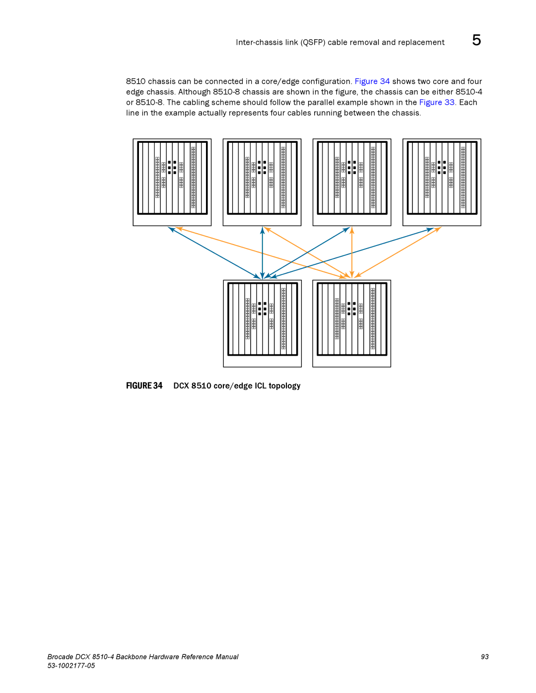
8510 chassis can be connected in a core/edge configuration. Figure 34 shows two core and four edge chassis. Although
FIGURE 34 DCX 8510 core/edge ICL topology
Brocade DCX | 93 |
|
5 |
8510 chassis can be connected in a core/edge configuration. Figure 34 shows two core and four edge chassis. Although
Brocade DCX | 93 |
|