A Environmental regulation compliance
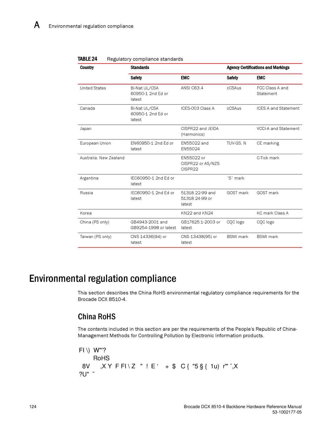
TABLE 24 | Regulatory compliance standards |
|
| ||
|
|
|
|
| |
Country |
| Standards |
| Agency Certifications and Markings | |
|
|
|
|
|
|
|
| Safety | EMC | Safety | EMC |
|
|
|
|
|
|
United States |
| ANSI C63.4 | cCSAus | FCC Class A and | |
|
|
|
| Statement | |
|
| latest |
|
|
|
|
|
|
|
|
|
Canada |
| cCSAus | ICES A and Statement | ||
|
|
|
|
| |
|
| latest |
|
|
|
|
|
|
|
|
|
Japan |
|
| CISPR22 and JEIDA |
| |
|
|
| (Harmonics) |
|
|
|
|
|
|
| |
European Union | EN55022 and | CE marking | |||
|
| latest | EN55024 |
|
|
|
|
|
|
| |
Australia, New Zealand |
| EN55022 or |
| ||
|
|
| CISPR22 or AS/NZS |
|
|
|
|
| CISPR22 |
|
|
|
|
|
|
|
|
Argentina |
|
| “S” mark |
| |
|
| latest |
|
|
|
|
|
|
|
|
|
Russia |
| GOST mark | GOST mark | ||
|
| latest |
|
| |
|
|
| latest |
|
|
|
|
|
|
|
|
Korea |
|
| KN22 and KN24 |
| KC mark Class A |
|
|
|
|
| |
China (PS only) | CQC logo | CQC logo | |||
|
| latest |
|
| |
|
|
|
|
| |
Taiwan (PS only) | CNS 14336(94) or | CNS 13438(95) or | BSMI mark | BSMI mark | |
|
| latest | latest |
|
|
|
|
|
|
|
|
Environmental regulation compliance
This section describes the China RoHS environmental regulatory compliance requirements for the Brocade DCX
China RoHS
The contents included in this section are per the requirements of the People's Republic of China- Management Methods for Controlling Pollution by Electronic Information products.
RoHS
124 | Brocade DCX |
|