| Appendix | |
Port Numbering Template | D | |
|
|
|
Print or copy the following templates in this appendix and use them to document the port numbering pattern for the Brocade DCX
•
•
•
•
•
•
•
•
1 | 2 | 3 |
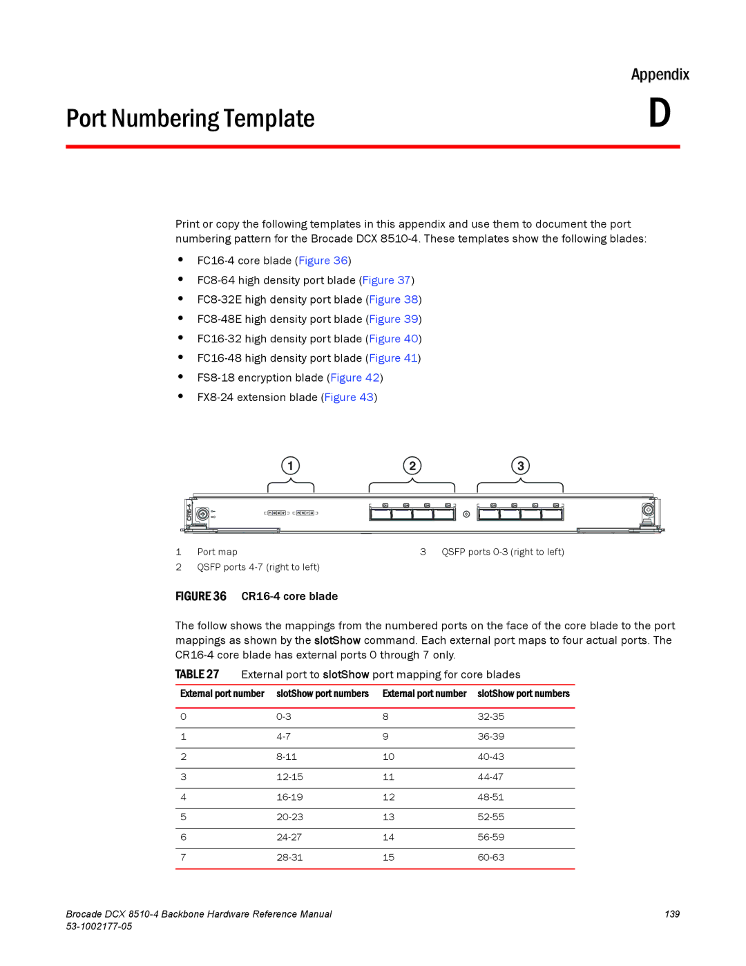
1Port map
2QSFP ports
3 QSFP ports
FIGURE 36 CR16-4 core blade
The follow shows the mappings from the numbered ports on the face of the core blade to the port mappings as shown by the slotShow command. Each external port maps to four actual ports. The CR16-4 core blade has external ports 0 through 7 only.
TABLE 27 External port to slotShow port mapping for core blades
External port number | slotShow port numbers | External port number | slotShow port numbers |
|
|
|
|
0 | 8 | ||
|
|
|
|
1 | 9 | ||
|
|
|
|
2 | 10 | ||
|
|
|
|
3 | 11 | ||
|
|
|
|
4 | 12 | ||
|
|
|
|
5 | 13 | ||
|
|
|
|
6 | 14 | ||
|
|
|
|
7 | 15 | ||
|
|
|
|
Brocade DCX | 139 |
|