5 Brocade DCX 8510-4 chassis removal and replacement
FID 1 1 1 1 1 128 128 128 128 128 <output truncated>
switch:admin>
2.Determine any differences between the information in the SANafter.txt file and the information in the SANbefor.txt file created earlier. In particular, look for differences in the following:
•Device types
•Number of devices
•ISL and port states
•Number of switches in the fabric
3.Resolve any issues or unintentional changes to the Brocade DCX
•If there are any mechanical problems, try reseating the associated component.
•If the configuration information is not correct for the Brocade DCX
•If other issues exist, contact your support provider.
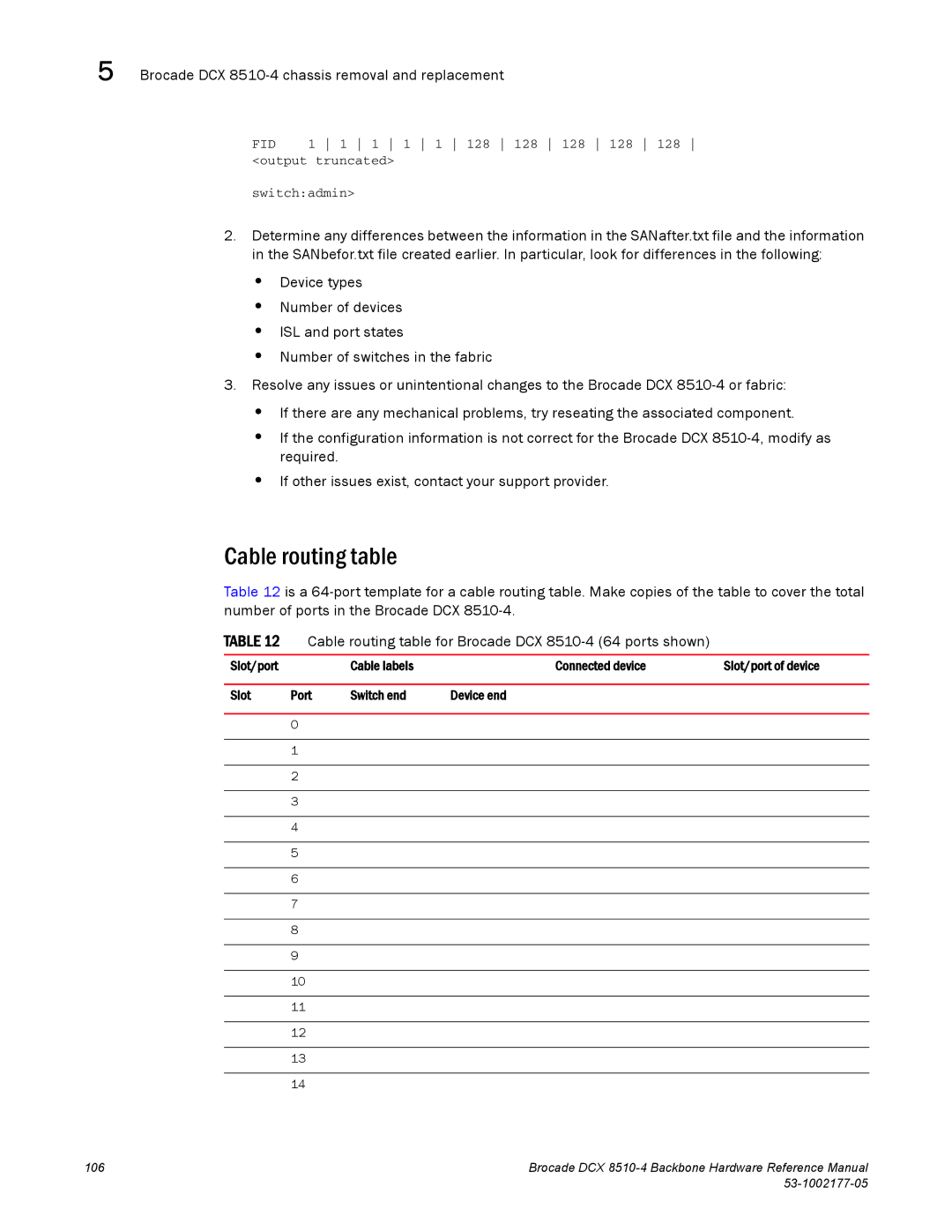
Cable routing table
Table 12 is a
TABLE 12 | Cable routing table for Brocade DCX |
| ||
|
|
|
|
|
Slot/port |
| Cable labels | Connected device | Slot/port of device |
|
|
|
|
|
Slot | Port | Switch end | Device end |
|
0
1
2
3
4
5
6
7
8
9
10
11
12
13
14
106 | Brocade DCX |
|