Determining the status of a power supply | 4 |
TABLE 5 CR blade LED descriptions (Continued)
LED purpose | Color | Status | Recommended action |
|
|
|
|
QSFP | No light (LED is off) | No QSFP module, all four | No action needed if the QSFP is not |
connector |
| QSFP ports are disabled | installed or |
status LED |
|
| verify that the QSFP is fully inserted. |
|
|
|
|
| Steady amber | QSFP module is in, all four | Ensure that the cable is properly |
|
| ports have no signal/no | connected. If the LED remains |
|
| sync. | amber, consult the Brocade DCX |
|
|
|
Blinking amber | Port is disabled or faulted, |
| FC link activity, segmented, |
| loopback mode, also |
| during transition between |
| cable plug in and all four |
| ports online. |
Check for console messages or wait for all four ports to come online.
Steady green | QSFP module is in and all No action needed. |
| ports are online. |
|
|
Refer to Figure 36 and Table 27 for a map of the ports and a table of external ports to internal ports as shown in the slotShow command
Determining the status of a power supply
Complete the following steps to determine the status of a power supply.
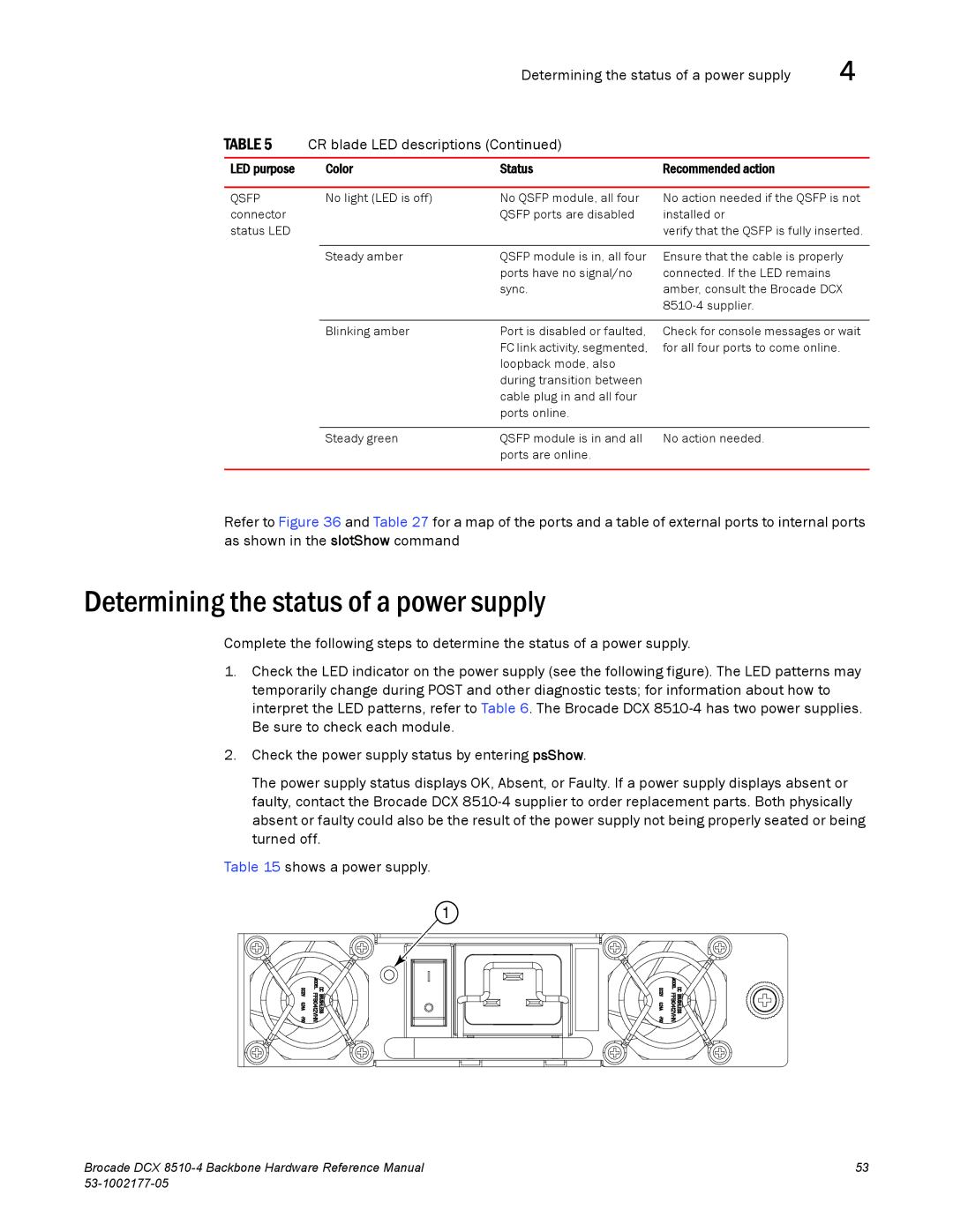
1.Check the LED indicator on the power supply (see the following figure). The LED patterns may temporarily change during POST and other diagnostic tests; for information about how to interpret the LED patterns, refer to Table 6. The Brocade DCX
2.Check the power supply status by entering psShow.
The power supply status displays OK, Absent, or Faulty. If a power supply displays absent or faulty, contact the Brocade DCX
Table 15 shows a power supply.
1 |
Brocade DCX | 53 |
|