4 Determining the status of a control processor blade (CP8)
Determining the status of a control processor blade (CP8)
Complete the following steps to determine the status of a control blade (CP8)
1.Check the LED indicators on the CP blade (Figure 13). The LED patterns may temporarily change during POST and other diagnostic tests. For information about how to interpret the LED patterns, see Table 4.
2.Check the port blade status by entering slotShow and haShow.
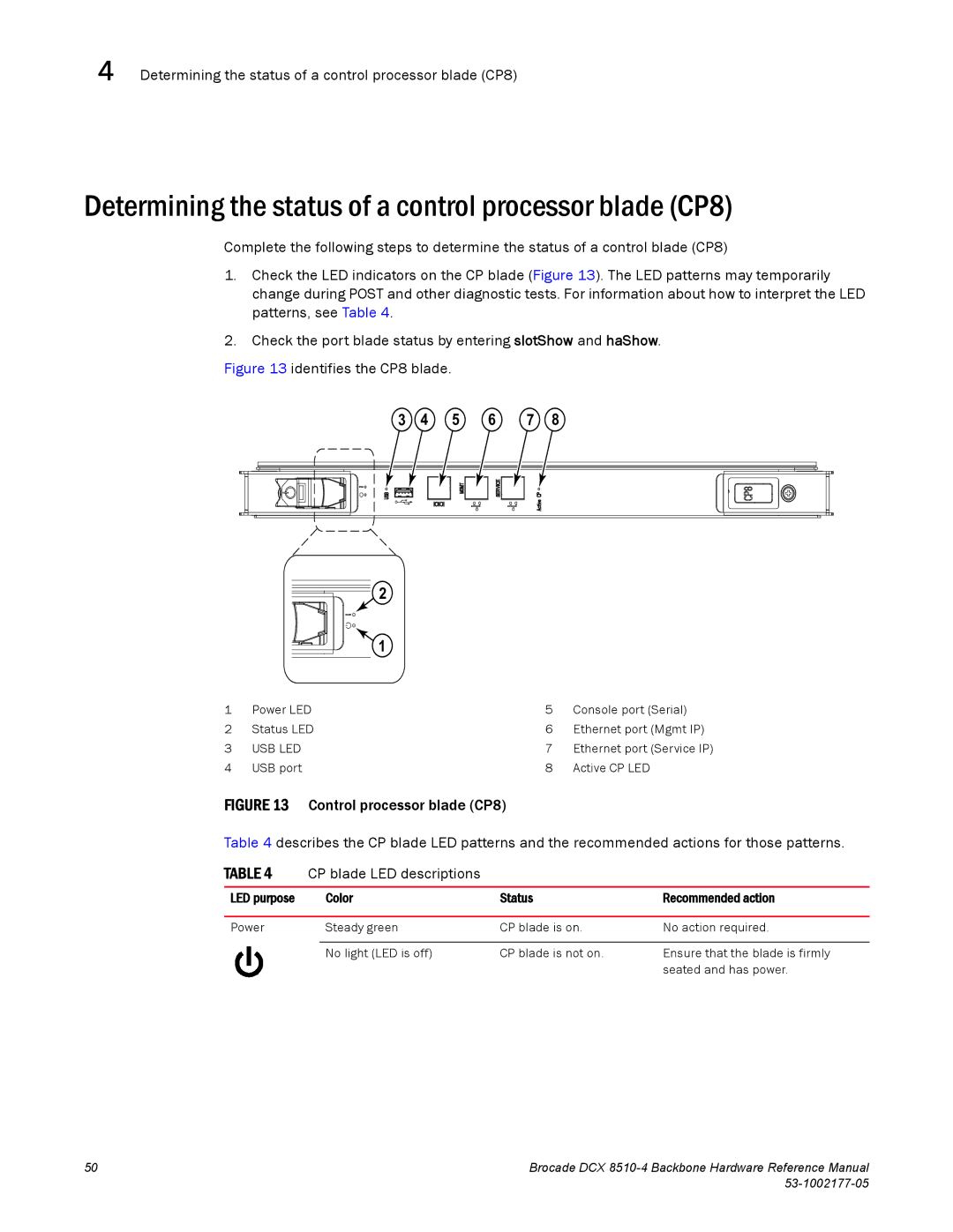
Figure 13 identifies the CP8 blade.
3 4 5 6 7 8
2
1
1 | Power LED | 5 | Console port (Serial) |
2 | Status LED | 6 | Ethernet port (Mgmt IP) |
3 | USB LED | 7 | Ethernet port (Service IP) |
4 | USB port | 8 | Active CP LED |
FIGURE 13 Control processor blade (CP8)
Table 4 describes the CP blade LED patterns and the recommended actions for those patterns.
TABLE 4 | CP blade LED descriptions |
|
| |
|
|
|
|
|
LED purpose |
| Color | Status | Recommended action |
|
|
|
|
|
Power |
| Steady green | CP blade is on. | No action required. |
|
|
|
|
|
|
| No light (LED is off) | CP blade is not on. | Ensure that the blade is firmly |
|
|
|
| seated and has power. |
50 | Brocade DCX |
|