4 Determining the status of a core switch blade (CR16-4)
2 | 3 | 4 |
1
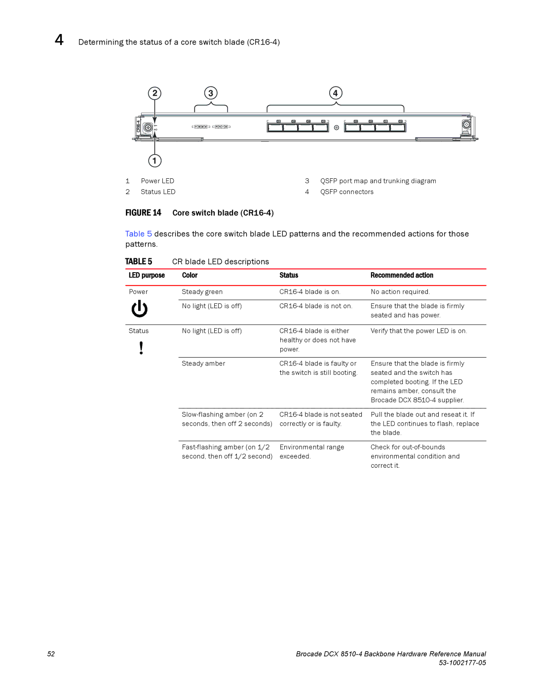
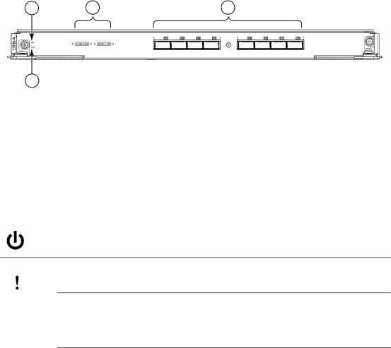
1 | Power LED | 3 | QSFP port map and trunking diagram |
2 | Status LED | 4 | QSFP connectors |
FIGURE 14 Core switch blade (CR16-4)
Table 5 describes the core switch blade LED patterns and the recommended actions for those patterns.
TABLE 5 | CR blade LED descriptions |
|
| |
|
|
|
|
|
LED purpose |
| Color | Status | Recommended action |
|
|
|
|
|
Power |
| Steady green | No action required. | |
|
|
|
|
|
|
| No light (LED is off) | Ensure that the blade is firmly | |
|
|
|
| seated and has power. |
Status | No light (LED is off) |
Verify that the power LED is on. | |
healthy or does not have |
|
power. |
|
Steady amber | |
| the switch is still booting. |
Ensure that the blade is firmly seated and the switch has completed booting. If the LED remains amber, consult the Brocade DCX
seconds, then off 2 seconds) | correctly or is faulty. |
Pull the blade out and reseat it. If the LED continues to flash, replace the blade.
Environmental range | Check for | |
second, then off 1/2 second) | exceeded. | environmental condition and |
|
| correct it. |
52 | Brocade DCX |
|