Manuals
/
Brocade Communications Systems
/
Computer Equipment
/
Computer Hardware
Brocade Communications Systems
manual
Brocade DCX 8510-4 hardware components
Models:
DCX 8510-4
1
25
168
168
Download
168 pages
16.56 Kb
22
23
24
25
26
27
28
29
Troubleshooting
Specs
Faulty CP blade indicators
Configuring the Brocade DCX
Diagnostics
Command syntax conventions
Removing a blower assembly
Setting the domain ID
Checklist
Weight
Page 25
Image 25
Brocade DCX
8510-4
hardware components
1
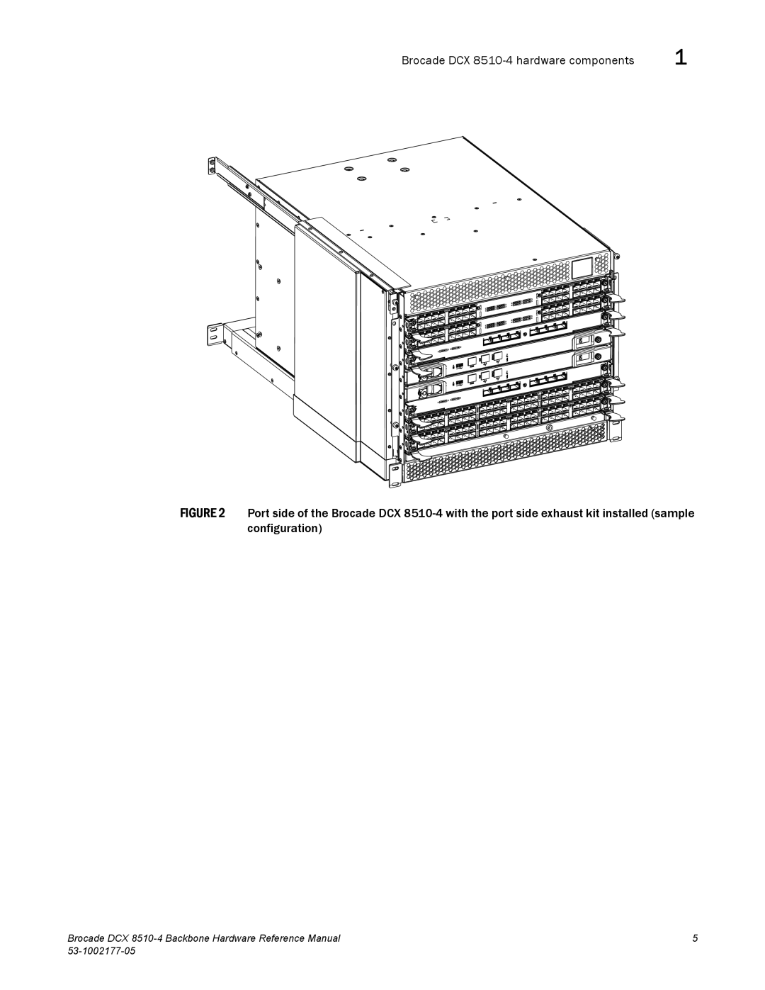
FIGURE 2
Port side of the Brocade DCX
8510-4
with the port side exhaust kit installed (sample configuration)
Brocade DCX
8510-4
Backbone Hardware Reference Manual
5
53-1002177-05
Page 24
Page 26
Page 25
Image 25
Page 24
Page 26
Contents
Brocade DCX 8510-4 Backbone
Brocade Communications Systems, Incorporated
Brocade DCX 8510-4 Backbone Hardware Reference Manual
Brocade DCX 8510-4 Backbone Hardware Reference Manual
Contents
This chapter Monitoring overview
Chapter Logging In and Configuring the Brocade DCX
Chapter Removal and Replacement Procedures
Appendix a Specifications
Troubleshooting
Diagnostics
This appendix
FS8-18 blade FX8-24 blade
Brocade DCX 8510-4 Backbone Hardware Reference Manual
Figures
Page
Tables
Page
How this document is organized
This chapter
What’s new in this document
Supported hardware and software
Document conventions
Text formatting
Command examples
Command syntax conventions
Command Option, option Argument, arg
Show WWN
Brocade resources
Additional information
Corporation Referenced Trademarks and Products
Other industry resources
Getting technical help
Documentation@brocade.com
Document feedback
Brocade DCX 8510-4 Backbone Overview
Brocade DCX 8510-4 features
Brocade DCX 8510-4 hardware components
Page
Port side of the Brocade DCX
Port side of the Brocade DCX 8510-4 sample configuration
Brocade DCX 8510-4 hardware components
Nonport side of the Brocade DCX
Description Name Function
Brocade DCX 8510-4 blades
Reliability
High availability
Software features
Serviceability
Security
SSHv2 using AES, 3DES, RSA Https using AES SNPMv3
Network manageability
Network manageability
Time and items required
Installation of the Brocade DCX
Installation task Time estimate Items required
Preparing for Brocade DCX 8510-4 installation
Page
Unpacking and installing the Brocade DCX
Unpacking and installing the Brocade DCX
Use safe lifting practices when moving the product. C015
Items included with the Brocade DCX
Items included with the Brocade DCX
Providing power to the Brocade DCX
Providing power to the Brocade DCX
Port numbering
Cable management
Chassis slots
High density cabling
Installing inter-chassis link Qsfp cables optional
Cable management
Configuring the Brocade DCX
Logging In and Configuring the Brocade DCX
Establishing a serial connection to the Brocade DCX
Illustrates the flow of the basic configuration tasks
Proceed to the next task
Logging in to the serial console port
Parameter Value
Configuring the IP addresses
Establishing an Ethernet connection to the Brocade DCX
SwDiradmin ipaddrset -chassis Ethernet IP Address 0.0.0.0
Customizing a chassis name
Customizing a switch name
Record the new name for reference
Setting the date and time
Setting the domain ID
Setting the date
Enter configure
You are prompted to select a general location
Setting the time zone
Verifying the PID mode
Verifying the PID mode
Synchronizing local time
Installing transceivers and attaching cables
Determining installed software licenses
Installing SFP+ and mSFP transceivers and cables
Installing Qsfp transceivers and cables
OFF
Managing cables
Managing cables
ConfigShow IpaddrShow LicenseShow SwitchShow
Powering off the Brocade DCX
Powering off the Brocade DCX
Powering off the Brocade DCX
Monitoring overview
Monitoring System Components
820000 Online
SW Blade
AP Blade
AGC2M03FR7T
Illustrates the FC8-64 port blade
Blade illustrations
FC8-32E port blade
FC16-32 port blade
FS8-18 encryption blade
Color Status Recommended action
LED purpose Color Status Recommended action
PortCfgPersistentEnable
Determining the status of a control processor blade CP8
Determining the status of a control processor blade CP8
Determining the status of a core switch blade CR16-4
Determining the status of a core switch blade CR16-4
Qsfp
Determining the status of a power supply
Determining the status of a blower assembly
Determining the status of a blower assembly
Determining the status of a WWN card
Determining the status of a WWN card
WWN unit fails to power on
Type of message Sample error message
WWN bezel logo plate for DCX
Determining the status of a WWN card
Introduction
ESD precautions
Chassis door removal and replacement
Chassis door removal and replacement
Time and items required
Removing a chassis door
Removing a cable management finger assembly
Vertical cable management fingers removal and replacement
Vertical cable management fingers removal and replacement
Replacing a cable management finger assembly
Removing a blade
Replacing a blade
Blade filler panel removal and replacement
Blade filler panel removal and replacement
Removing a filler panel
Control processor blade CP8 removal and replacement
Control processor blade CP8 removal and replacement
Replacing a filler panel
Faulty CP blade indicators
Recording critical Brocade DCX 8510-4 information
Removing a control processor blade CP8
Replacing a control processor blade CP8
Verifying operation of the new CP blade
Downloading firmware from an FTP server
Downloading firmware from a USB device
Brocade DCX 8510-4 Backbone Hardware Reference Manual
Completing the replacement
Faulty core switch blade indicators
Core switch blade CR16-4 removal and replacement
Removing a core switch blade CR16-4
Replacing a core switch blade CR16-4
Power supply removal and replacement
Power supply removal and replacement
Removing a power supply
Identifying power supplies
Replacing a power supply
Blower assembly removal and replacement
Use this procedure to remove and replace a blower assembly
Removing a blower assembly
Replacing a blower assembly
WWN card removal and replacement
Preparing for the WWN card replacement
Verifying the need for replacement
Removing the WWN bezel logo plate and WWN card
Brocade DCX 8510-4 Backbone Hardware Reference Manual
Replacing the WWN card and WWN bezel logo plate
Transceiver removal and replacement
Removing an SFP+ transceiver
Removing and replacing an mSFP optical transceiver
Replacing an SFP+ transceiver
Use this procedure to remove and replace a Qsfp cable
Inter-chassis link Qsfp cable removal and replacement
Qsfp cable insertion
Replacing an ICL cable
Removing an ICL cable
Complete the following steps to replace a Qsfp cable
Possible ICL configurations
Chassis 1 DCX Chassis 2 DCX
DCX 8510 core/edge ICL topology
DCX 8510 full mesh ICL topology
Brocade DCX 8510-4 chassis removal and replacement
Faulty Brocade DCX 8510-4 chassis indicators
Recording critical Brocade DCX 8510-4 and SAN information
Critical information checklist
Switch
NsShow NsAllShow SwitchShow -qsfp FabricShow
Sysshutdown
Disconnecting from the network and fabric
Removing components from the chassis
Installing the replacement chassis
Installing components into the new chassis
Switchadmin configdownload -all
Downloading the configuration
Verifying correct operation of the system
Reconnecting the system to the network and fabric
NsShow NsAllShow SwitchShow FabricShow
Verifying correct configuration of the fabric
Lscfg --showif using the Virtual Fabric feature
Cable routing table for Brocade DCX 8510-4 64 ports shown
Cable routing table
Slot/port
Slot Port Switch end Device end
Page
This appendix
General specifications
Description
FeatureDescription
System architecture General specifications
System architecture
System size and weight System architecture
System size and weight
Feature Description
System blade and FRU weights System size and weight
System blade and FRU weights
System Size or weight
Weight
Facility requirements
Facility requirements System FRU weights
Environmental requirements
Condition Acceptable range during operation
Power specifications
Fibre Channel port specifications
Units Power Draw
SpecificationValue
Blade or fan Maximum
Ports per blade Number of blades
Power cords Power demands per component
Power cords
Demand
VAC nominal
All locations
Power cords Power cord types international
Power cords Power cord types international
Power cord notice Japan Denan
Power cord notice
Data transmission ranges
Form factor Speed
Qualified cables for the FC8-64 port blade
Multimode media
Type Microns OM1 OM2 OM3 OM4
Regulatory compliance
Safety notices
KCC statement Republic of Korea
FCC warning US only
Vcci statement Japan
Bsmi statement Taiwan
Canadian requirements
CE statement
German statement
Laser compliance
Environmental regulation compliance
Safety
China RoHS
Country Standards
Environmental Protection Use Period Epup Disclaimer
Environmental regulation compliance
Environmental regulation compliance
Environmental regulation compliance
FS8-18 blade
Application and Encryption Blades
Fcip
FX8-24 blade
Page
FX8-24 blade
Diagnostics and Troubleshooting
Command Information displayed
Interpreting Post and boot results
Obtaining chassis and component status
Boot
Diagnostics
Troubleshooting the Brocade DCX
Troubleshooting
Issue Possible cause Recommended action
See the Fabric OS Administrator’s Guide for
Troubleshooting Troubleshooting the Brocade DCX
Source of the problem or replace the blade as
Port Numbering Template
Port Numbering Template
FC16-48 port blade
GbE ports FC ports Blade Power LED Blade Status LED
Index
144
145
RRP
147
Top
Page
Image
Contents