FY8-13EX-000
Copyright 1997 Canon INC
Introduction
Copyright 1997 Canon INC
Iii
System Configuration
General Description Copyright 1997 Canon INC
Contents
Image Formation System
Exposure System
Vii
PICK-UP/FEEDING System
Viii
Fixing System
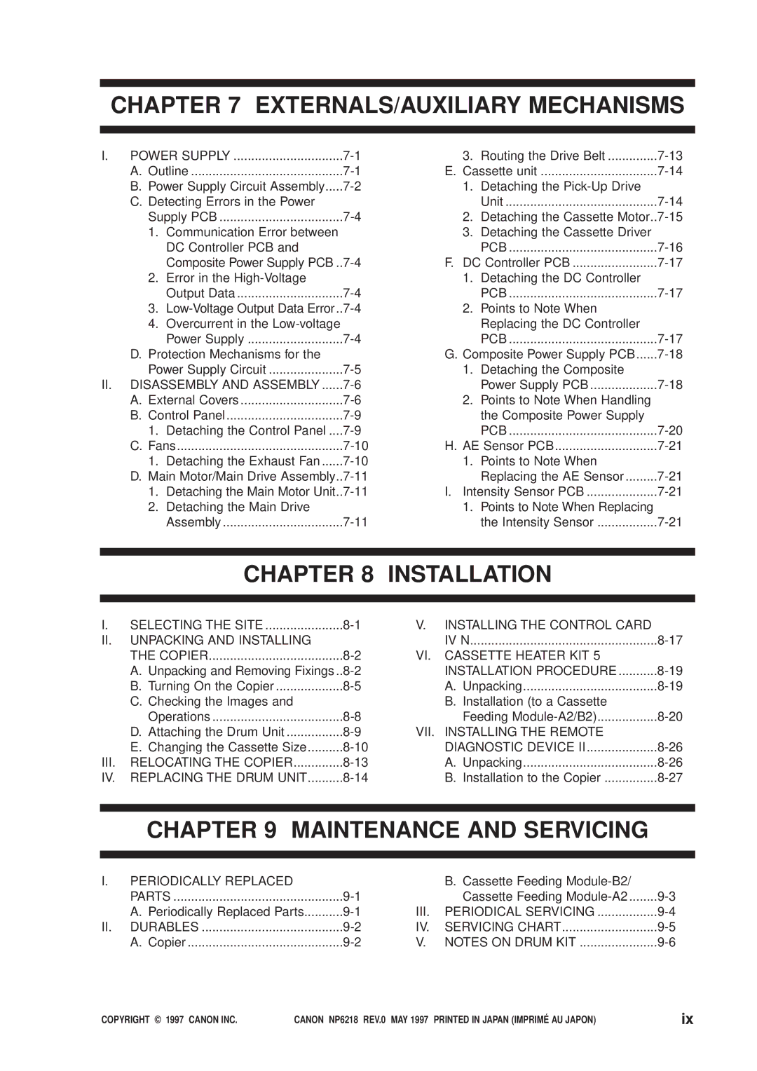
EXTERNALS/AUXILIARY Mechanisms
Installation
Maintenance and Servicing
II. Standards and ADJUSTMENTS..10-5
Troubleshooting
Arrangement and Functions
Xii
Appendix
Chapter General Description
Office amenities and ecology
Features
Practical basic features
Multiple front loading and multifeeder for space saving
System
II. Specifications
Copier
Type
Features
201 Standard Reproduction Ratios
Others
202 Copying Speed
Cassette Feeding Module-B2/Cassette Feeding Module-A2
Exterior View
III. Names of Parts
Body
Cross Section
Cassette Feeding Module-A2
Control Panel
IV. Operation
Operation Mode
Making Two-Sided/Overlay Copies manual
Outline
User Mode
Changing the Auto Clear Time
Common Operations Keys to Use in User Mode
Changing the Auto Power-Off Time
Operation
Reference
Zoom Fine-Adjustment
Turning On and Off the Auto Cassette Change Mechanism
Cleaning the Feeder with ADF installed-option
Initializing User Mode
Selecting the Density Adjustment Method for Standard Mode
Quick Guide to User Mode
Handling the Toner Bottle
VI. Routine Maintenance by the User
Outline
VII. Image Formation
General Description
General Description Copyright 1997 Canon INC
Chapter Basic Operation
Functional Construction
Basic Construction
CPU
Outline of the Electrical Circuitry
Stby Intr Scfw Scrv Lstr AER
Basic Sequence of Operations 2 copies continuous, AE
Mechanism
Main Motor Control Circuit
Inputs to the DC Controller PCB 1/3
Inputs to the DC Controller PCB
CSZ3 CSZ4
Inputs to the DC Controller PCB 2/3
Inputs to the DC Controller PCB 3/3
Outputs from the DC Controller PCB 1/3
Outputs from the DC Controller PCB
Mfpucld
Outputs from the DC Controller PCB 2/3
Hefd
Outputs from the DC Controller PCB 3/3
CS2
Inputs to and Outputs from the 1-Cassette Unit Driver PCB
C3VPD
Inputs to and Outputs from the 2-Cassette Unit Driver PCB
C2PUCLD
Basic Operation Copyright 1997 Canon INC
Chapter Exposure System
Varying the Reproduction Ratio
II. Lens Drive System
Chsld
Driving the Lens Motor
Lens Motor Drive Circuit
Keeping the Lens Motor Stationary
Stby Intr Scfw Scrv Lstr AER
Basic Sequence of Operations lens drive system non-Direct
Driving the Scanner
III. Scanning Drive System
Basic Sequence of Operations scanner
Relationship between the Scanner Sensor and Signals
Driving the Scanner Motor Outline
Exposure System
Detaching the Scanner Drive Motor
IV. Disassembly and Assembly
Scanner Drive Assembly
Detaching the Scanner Cable
Exposure System
Assembling the Mirror Position Tool
Routing the Scanner Cable
Set screws Loosen the set Screw to free Totation Pulley
Hook Wirespring Cable
Frontrear
Cleaning the Scanner No Mirror
Detaching the Lens Drive Motor
Lens Drive Assembly
Exposure System
Routing the Lens Cable
421 Lens Drive Assembly
Adjusting the Position of the Change Solenoid
Exposure System Copyright 1997 Canon INC
Chapter Image Formation System
Processes
Composite Power Supply PCB DC controller PCB
T101
On on
Basic Sequence of Operations image formation system
Flprht
Controlling the Scanning Lamp
Pre-Heating Control scanning lamp
Turning On and Off the Scanning Lamp
OFF
Controlling the Intensity of the Scanning Lamp FL1
Controlling the Fluorescent Lamp Heater
Fluorescent Lamp Protection Mechanism
Fluorescent Lamp Automatic
Mpwm
Controlling the Primary Charging Roller Bias
Turning On and Off the Primary Charging Roller Bias
Image Formation System
Reference Bias Atvc
Cleaning Bias
Controlling the Transfer Roller Bias
Transfer Bias
Tfwon Tfwpwm Tfws Trevon
Current Limiter Circuit transfer bias
Current Limiter Circuit cleaning bias
Turning On and Off the Transfer Roller Bias
Controlling the Transfer Bias to a Constant Voltage
Controlling the Static Eliminator Bias
Ensuring Proper Separation of Thin Paper
Switching the Static Eliminator Bias Voltage Level
Bssld
Controlling Blank Exposure
Blanking Whiting of Non-Image Areas for Reduction
Primary Charging Roller Cleaning Operation
Controlling the Primary Corona Roller Cleaning Mechanism
Releasing the Transfer Roller
II. Developing Assembly and Cleaning Assembly
Controlling the Toner Level Detection
Stby
Mpwm
Controlling the Development Bias
Turning On and Off the AC Component of the Development Bias
Control Method
Automatic Control of Copy Density
207 Area Read by the AE Sensor Reference
AE Adjustment
Detaching the Scanning Lamp/Fluorescent Lamp Heater
III. Disassembly and Assembly
Illumination Assembly
Image Formation System
~5mm 60mm
306 front view
Detaching the Blank Exposure Assembly
Detaching the Blank Exposure Lamp
Detaching the Blank Shutter Solenoid
314a
Positioning the Blank Shutter Solenoid
Positioning the Left/Right Margin
Routing the Blanking Cable
Detaching the Drum Unit
Drum Unit
Cleaning
Detaching the Primary Corona Assembly
Primary Corona Assembly
Cleaning the Cleaning Pad and the Primary Corona Roller
Positioning the Solenoid for the Primary Charging Roller
Attaching the Drum Heater
Transfer Charging Assembly
Detaching the Transfer Roller
Image Formation System
Image Formation System
Developing System
Removing the Developing Assembly
Removing the Blade Assembly
Removing the Developing Cylinder Side Seal
Image Formation System
Image Formation System
Installing the Side Seal and the Blade Assembly
Image Formation System
Chapter PICK-UP/FEEDING System
PICK-UP/FEEDING System
PS4
II. PICK-UP Operation Copier
Sequence of Operations pick-up/feeding assembly A4, 2 copies
Pick-Up Operation
III. PICK-UP from the Cassette Feeding MODULE-A2
Intr Scfw Scrv Scfw Scrv Lstr
Sequence of Operations cassette 2 A4, 2 copies
PS5
IV. Multifeeder
Identifying the Size of Paper on the Multifeeder
Intr Scfw Scrv Scfw Lstr
Sequence of Operations multifeeder A4, 2 copies
Identifying the Cassette Size
Guide plate horizontal Paper size lever Guide plate vertical
VI. Identifying Jams
Pre-Registration Delay Jam
Pre-Registration Stationary Jam
Pre-Registration Timing Jam
Separation Stationary Jam
Separation Delay Jam
Delivery Stationary Jam
Delivery Delay Jam
Detaching the Pick-Up Roller Unit
VII. Disassembly and Assembly
Pick-Up Assembly
PICK-UP/FEEDING System
PICK-UP/FEEDING System
Detaching the Pick-Up Roller
Detaching the Pick-Up Clutch
Points to Note When Attaching the Pick-Up Roller
Detaching the Separation Pad
Pick-Up from the Cassette
Adjusting the Left/Right Registration
Detaching the Multifeeder Assembly
Multifeeder Assembly
Detaching the Multifeeder Pick-Up Roller Unit
Detaching the Multifeeder Pick-Up Roller
Front of copier
Detaching the Multifeeder Drive Unit
Detaching the Multifeeder Clutch
Positioning the Multifeeder Assembly paper guide plate cam
Adjusting the Left/Right Registration
Detaching the Upper Registration Roller
Registration Roller Assembly
Detaching the Registration Clutch
PICK-UP/FEEDING System
Detaching the Lower Registration Roller
Detaching the Feeding Belt
Feeding Assembly
PICK-UP/FEEDING System
Detaching/Attaching the Pick-Up Roller
Cassette Feeding Module
Detaching the Copier from the Cassette Feeding Module
Chapter Fixing System
Basic Operations
Pwsw
Controlling the Fixing Heater Temperature
Reference
Controlling the Supply Power for the Fixing Heater
Thermal Fuse FU1
Detecting Overheating at the End of the Fixing Heater
Protection Mechanism
Thermistor TH1, TH2
Correcting Displacement of the Fixing Film
OFF
Fixing System
Controlling the Fixing Film Motor
Construction1
II. Disassembly and Assembly
Fixing Assembly
Detaching the Upper Fixing Unit
Fixing System
Fixing System
Fixing System
Fixing System
Fixing System
Fixing System
Fixing System
Points to Note When Attaching the Heater Connector
Points to Note When Attaching the Fixing Film
Adjusting the Fixing Film Drive Roller Pressure
Points to Note When Replacing the Fixing Upper Unit
Fixing System
Detaching the Lower Fixing Unit
Fixing System
Adjusting the Lower Fixing Roller Nip
Measuring the Nip
Delivery Assembly
Fixing System Copyright 1997 Canon INC
Chapter
Power Supply
Power Supply Circuit Assembly
EXTERNALS/AUXILIARY Mechanisms Copyright 1997 Canon INC
Overcurrent in the Low-voltage Power Supply
Detecting Errors in the Power Supply PCB
Error in the High-Voltage Output Data
Low-Voltage Output Data Error
Protection Mechanisms for the Power Supply Circuit
External Covers
Cover
EXTERNALS/AUXILIARY Mechanisms
Detaching the Control Panel
Detaching the Exhaust Fan
Fans
Detaching the Main Motor Unit
Main Motor/Main Drive Assembly
Detaching the Main Drive Assembly
EXTERNALS/AUXILIARY Mechanisms
Routing the Drive Belt
Detaching the Pick-Up Drive Unit
Cassette unit
Detaching the Cassette Motor
Detaching the Cassette Driver PCB
Detaching the DC Controller PCB
Points to Note When Replacing the DC Controller PCB
DC Controller PCB
Detaching the Composite Power Supply PCB
Composite Power Supply PCB
EXTERNALS/AUXILIARY Mechanisms
Points to Note When Handling the Composite Power Supply PCB
Intensity Sensor PCB
Points to Note When Replacing the AE Sensor
Points to Note When Replacing the Intensity Sensor
AE Sensor PCB
EXTERNALS/AUXILIARY Mechanisms Copyright 1997 Canon INC
Chapter Installation
Selecting the Site
Unpacking and Removing Fixings
II. Unpacking and Installing the Copier
Installation
Installation
Turning On the Copier
Installation
Installation
Checking the Images and Operations
Attaching the Drum Unit
Changing the Cassette Size
A5 R A4
Set the paper size plates selected in step
Direct position refers to
III. Relocating the Copier
IV. Replacing the Drum Unit
Go through the following when replacing the drum unit
Installation
Installation
Installing the Control Card IV N
Installation
Unpacking
VI. Cassette Heater KIT 5 Installation PROCE- Dure
Installation to a Cassette Feeding Module-A2/B2
Screws
Tie-wrap Connector Cord clamp
Copiers connector Molded member Copiers base plate
Relay harness
Installation
VII. Installing the Remote Diagnostic Device
Installation to the Copier
Installation
Installation
SW2 SW3
LED1 LED2 LED3 BAT1
AII
Bits on SW2 Setting
SW2-3
Shift bit 6 of the DIP switch 2 !9on the RDD’s PCB to OFF
Installation
Installation
Installation
Chapter Maintenance and Servicing
Periodically Replaced Parts
Periodically Replaced Parts
II. Durables
Pick-up roller FB2-2251-000 100,000
III. Periodical Servicing
IV. Servicing Chart
Maintenance and Servicing
Chapter Troubleshooting
10-1
Guide to Troubleshooting Tables
10-2
10-3
Maintenance and Inspection
Image Adjustment Basic Procedure
10-4
Periodical Servicing
10-5
II. Standards and Adjustments
Image Adjustment
10-6
10-7
10-8
10-9
Adjusting the Left/Right Margin No left/right margin
10-10
Adjusting the Scanning Lamp Intensity
10-11
10-12
210 DC Controller PCB
10-13
10-14
10-15
Exposure System
Routing the Scanner Drive Cable
10-16
10-17
Adjusting the Scanner Cable Tension
Assembling the Mirror Positioning Tool
10-18
10-19
220 front view
10-20
Positioning the Change Solenoid
10-21
Image Formation System
10-22
Routing the Blank Shutter Cable
10-23
After Replacing the Drum Unit
10-24
10-25
Pick-Up/Feeding System
Orientation of the Pick-Up Roller
Orientation of the Multifeeder Pick-Up Roller
10-26
Positioning the Paper Guide Plate Cam multifeeder
10-27
Fixing System
10-28
236 rear view
10-29
Points to Note after Replacing the Fixing Upper Unit
10-30
Adjusting the Nip
10-31
Storing the Fixing Heater Resistance
240 Heater Stay Side Plate rear 10-32
Setting the Fixing Heater Temperature Control Value
10-33
Example
10-34
10-35
Electrical
After Replacing the PCB
Clearing the Back-Up RAM
10-36
Checking the Photointerrupters
10-37
Copier
PS9
10-38
10-39
Cassette Feeding Unit
10-40
10-41
10-42
10-43
Adjusting the Multifeeder Paper Width Sensor
10-44
Setting the Paper Size for the Universal Cassette
Initial Checks
III. Troubleshooting Image Faults
10-46
10-47
10-48
Samples of Image Faults
10-49
Troubleshooting Faulty Images
Copy is too light half-tone only
10-50
10-51
10-52
10-53
Copy is foggy overall
10-54
Copy has black lines vertical, fine
10-55
Copy has white spot vertical Copy has white lines vertical
10-56
Copy has white spots horizontal
10-57
Back of the copy is soiled
10-58
Copy has a fixing fault
15, 16, 17 The leading edge of the copy is displaced
10-59
Copy has a blurred image
10-60
Copy is foggy horizontal
10-61
Copy has poor sharpness
10-62
Copy is blank
Copy is solid black
10-63
IV. Troubleshooting Malfunctions
Troubleshooting Malfunctions
E000
10-64
E001
E002, E003
10-65
E004
E007
10-66
E010
E030
10-67
E064
E202 keys on control panel invalidated
10-68
10. E210
11. E220
12. E240
10-69
13. E261
14. E710, E711, E712, E717
15. E803
10-70
AC power supply is absent
10-71
DC power supply is absent
10-72
Blank shutter fails to move
Photosensitive drum fails to rotate
10-73
Pick-up operation fails from cassette
Pick-up operation from the multifeeder fails
10-74
Scanner fails to move forward/in reverse
Registration roller fails to rotate
10-75
Scanning lamp fails to turn on
Lens fails to move
10-76
Add paper indicator fails to turn off
Fixing heater fails to operate
Pre-exposure lamp fails to turn on
10-77
Jam message fails to turn off
10-78
Troubleshooting Feeding Problems
Jams copy paper
10-79
Pick-Up Assembly
Fixing/Delivery Assembly
Separation/Feeding Assembly
10-81
Feeding Faults
Double feeding
Wrinkling
10-82
VI ARRANGEMENT/FUNCTIONS of the Electrical Parts
Sensors
10-83
10-84
Clutches, Solenoids, and Switches
10-85
10-86
Motors, Heaters, and Lamps
10-87
10-88
PCBs
10-89
10-90
Cassette Feeding Module A2
10-91
Photointerrupter
10-92
Variable Resistors VR and Check Pins by PCB
DC controller PCB
10-93
Composite power supply PCB
10-94
VII. Service Mode
Using Service Mode
Activating Service Mode
Clearing Stored Error Code
Selecting a Service Mode
Using Adjustment Mode 3 and Specification Mode
Using Operation/Inspection Mode
10-96
Recording on the Service Mode Label
10-97
Control Display Mode
10-98
10-99
O Mode
10-100
No /202/203/204 Port C Digital Display
10-101
Port H Display
10-102
Adjustment Mode
10-103
10-104
10-105
Operation/Inspection Mode
10-106
10-107
Specification Settings Mode
10-108
Counter Mode
10-109
VIII. Self Diagnosis
10-110
E003
10-111
E210
10-112
10-113
E400
10-114
E500
10-115
10-116
Appendix
A4, 2 copies, Direct, from copier cassette
General Timing Chart
Signals and Abbreviations
Signals and Abbreviations
General Circuit Diagram
Copyright 1997 Canon INC
Special Tools
MEK
SOLVENTS/OILS
Canon INC
This publication is printed on 70% reprocessed paper