Chapter 1 Installing the Cisco Digital Media Encoder 2200
Installation
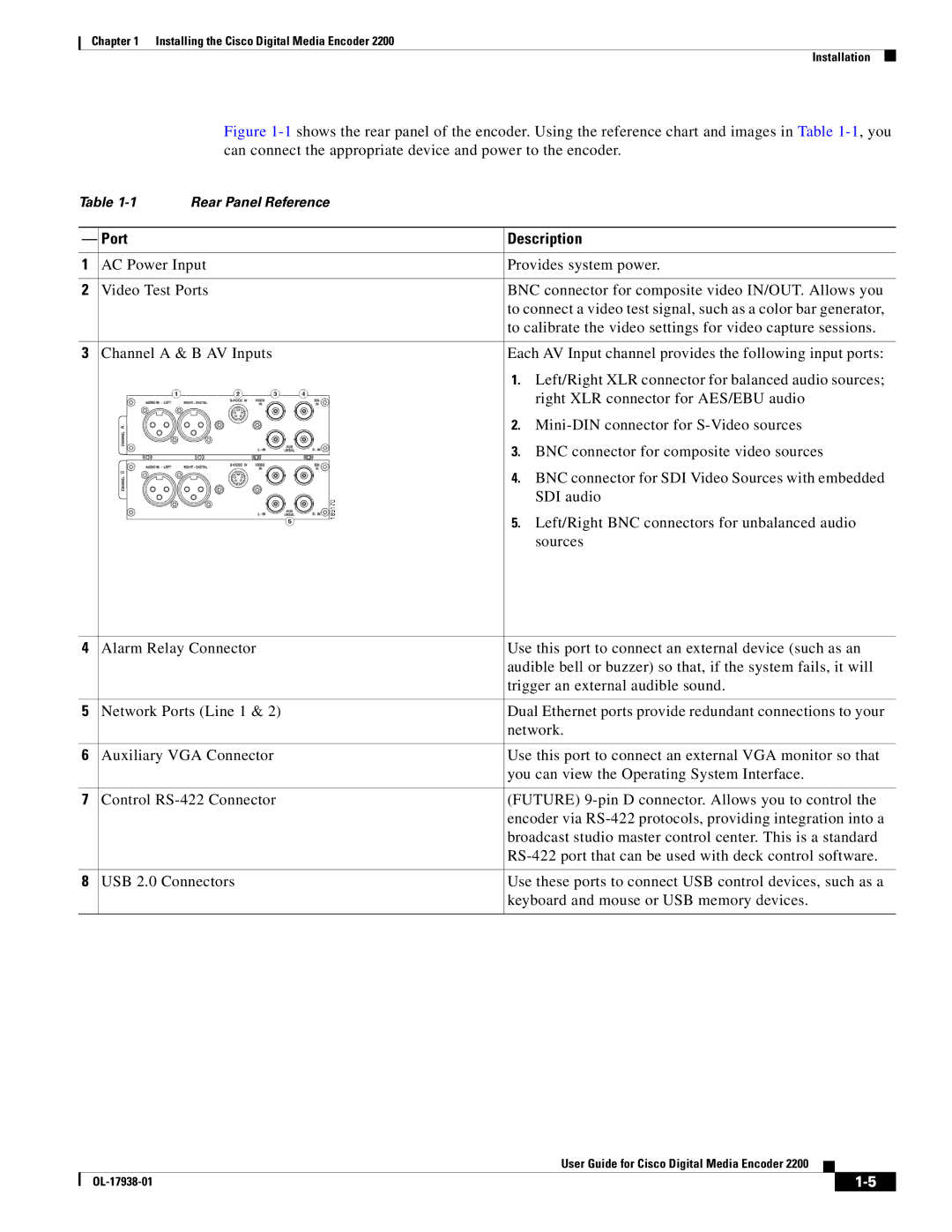
Figure 1-1 shows the rear panel of the encoder. Using the reference chart and images in Table 1-1, you can connect the appropriate device and power to the encoder.
Table | Rear Panel Reference |
| |
|
|
| |
— | Port |
| Description |
|
|
| |
1 | AC Power Input | Provides system power. | |
|
|
| |
2 | Video Test Ports | BNC connector for composite video IN/OUT. Allows you | |
|
|
| to connect a video test signal, such as a color bar generator, |
|
|
| to calibrate the video settings for video capture sessions. |
|
|
| |
3 | Channel A & B AV Inputs | Each AV Input channel provides the following input ports: | |
|
|
| 1. Left/Right XLR connector for balanced audio sources; |
|
|
| right XLR connector for AES/EBU audio |
|
|
| 2. |
|
|
| 3. BNC connector for composite video sources |
|
|
| 4. BNC connector for SDI Video Sources with embedded |
|
|
| SDI audio |
|
|
| 5. Left/Right BNC connectors for unbalanced audio |
|
|
| sources |
|
|
| |
4 | Alarm Relay Connector | Use this port to connect an external device (such as an | |
|
|
| audible bell or buzzer) so that, if the system fails, it will |
|
|
| trigger an external audible sound. |
|
|
| |
5 | Network Ports (Line 1 & 2) | Dual Ethernet ports provide redundant connections to your | |
|
|
| network. |
|
|
| |
6 | Auxiliary VGA Connector | Use this port to connect an external VGA monitor so that | |
|
|
| you can view the Operating System Interface. |
|
|
| |
7 | Control | (FUTURE) | |
|
|
| encoder via |
|
|
| broadcast studio master control center. This is a standard |
|
|
| |
|
|
| |
8 | USB 2.0 Connectors | Use these ports to connect USB control devices, such as a | |
|
|
| keyboard and mouse or USB memory devices. |
|
|
|
|
User Guide for Cisco Digital Media Encoder 2200
|
| ||
|
|
