| # of |
| Subnet Mask |
| CIDR |
| # of |
| # of |
| Total |
| Bits |
|
|
| Notation |
| Subnets |
| Hosts |
| Hosts |
2 | 255.255.192 | /18 | 2 | 16382 | 32764 | ||||||
3 | 255.255.224.0 | /19 | 6 | 8190 | 49140 | ||||||
4 | 255.255.240.0 | /20 | 14 | 4094 | 57316 | ||||||
5 | 255.255.248.0 | /21 | 30 | 2046 | 61380 | ||||||
6 | 255.255.252.0 | /22 | 62 | 1022 | 63364 | ||||||
7 | 255.255.254.0 | /23 | 126 | 510 | 64260 | ||||||
8 | 255.255.255.0 | /24 | 254 | 254 | 64516 | ||||||
9 | 255.255.255.128 | /25 | 510 | 126 | 64260 | ||||||
10 | 255.255.255.192 | /26 | 1022 | 62 | 63364 | ||||||
11 | 255.255.255.224 | /27 | 2046 | 30 | 61380 | ||||||
12 | 255.255.255.240 | /28 | 4094 | 14 | 57316 | ||||||
13 | 255.255.255.248 | /29 | 8190 | 6 | 49140 | ||||||
14 | 255.255.255.252 | /30 | 16382 | 2 | 32764 | ||||||
|
|
| Table |
|
| ||||||
|
|
|
|
|
|
|
|
|
|
|
|
| # of |
| Subnet Mask |
| CIDR |
| # of |
| # of |
| Total |
| Bits |
|
|
| Notation |
| Subnets |
| Hosts |
| Hosts |
| 2 |
| 255.255.255.192 |
| /26 |
| 2 |
| 62 |
| 124 |
| 3 |
| 255.255.255.224 |
| /27 |
| 6 |
| 30 |
| 180 |
| 4 |
| 255.255.255.240 |
| /28 |
| 14 |
| 14 |
| 196 |
| 5 |
| 255.255.255.248 |
| /29 |
| 30 |
| 6 |
| 180 |
| 6 |
| 255.255.255.252 |
| /30 |
| 62 |
| 2 |
| 124 |
Table
Setting up IP Interfaces
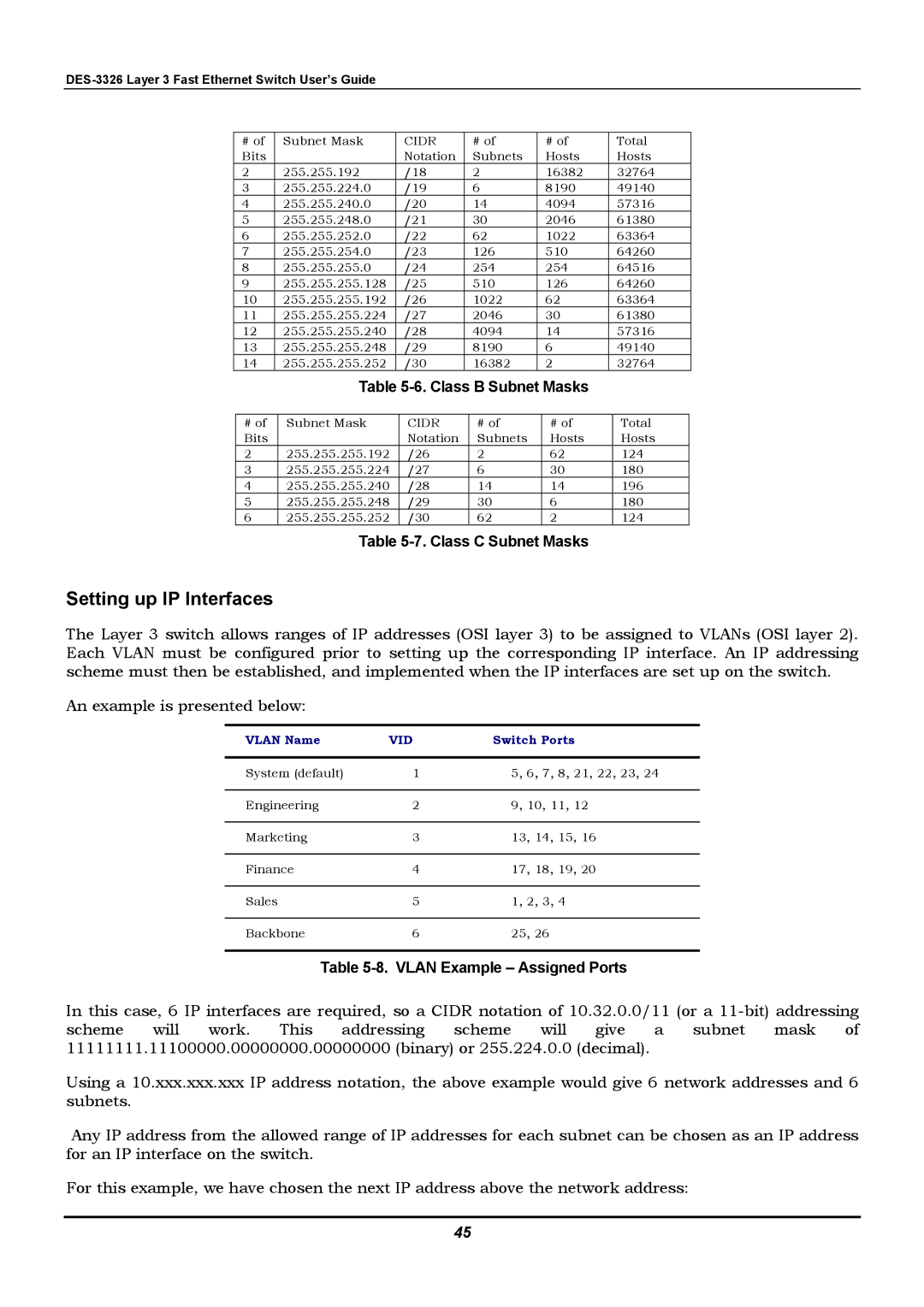
The Layer 3 switch allows ranges of IP addresses (OSI layer 3) to be assigned to VLANs (OSI layer 2). Each VLAN must be configured prior to setting up the corresponding IP interface. An IP addressing scheme must then be established, and implemented when the IP interfaces are set up on the switch.
An example is presented below:
VLAN Name | VID | Switch Ports |
|
|
|
System (default) | 1 | 5, 6, 7, 8, 21, 22, 23, 24 |
|
|
|
Engineering | 2 | 9, 10, 11, 12 |
|
|
|
Marketing | 3 | 13, 14, 15, 16 |
|
|
|
Finance | 4 | 17, 18, 19, 20 |
|
|
|
Sales | 5 | 1, 2, 3, 4 |
|
|
|
Backbone | 6 | 25, 26 |
Table 5-8. VLAN Example – Assigned Ports
In this case, 6 IP interfaces are required, so a CIDR notation of 10.32.0.0/11 (or a
Using a 10.xxx.xxx.xxx IP address notation, the above example would give 6 network addresses and 6 subnets.
Any IP address from the allowed range of IP addresses for each subnet can be chosen as an IP address for an IP interface on the switch.
For this example, we have chosen the next IP address above the network address:
45