Bar Code Label Printer
Page
Iii
Contributors
Page
Contents
Testing the Printer
Inspecting the Printer Cleaning the Printer
About Troubleshooting and Repair
Contents Adjusting the Printer
Error Handling
Miscellaneous Problems Vii
Replacing the Lithium Battery
Printer Maintenance Manual
Replacing Printer Components
Viii
Functional Description of the 3600 Software A-14
Appendix
Page
Before You Begin
Safety Summary
Purpose of This Manual
Who Should Read This Manual?
Xii
For information about
How This Manual Is Organized
Refer to
Xiii
Terms
Terms and Conventions
Conventions
Convention Description
Additional Information
Page
General Information
Page
Overview of the 3600 Printer
Printer Specifications
Features
Dimensions no options installed
Electrical Requirements
Media Specifications
Printhead Specifications
Ribbon Specifications
Self-Strip Specifications
Fonts and Graphics
Communications
Character Sets
Memory
Configuration
Factory Default Settings
Printer Options
Memory Expansion
Parallel Interface
Coax Interface
Network Connectivity
Kanji/Katakana Character Support
Principal Functional Parts
Media post TTR supply hub TTR takeup hub
Basic Printer Setup and Operation
Over-Temperature
Front Panel Operation
Media or System Faults
Checking the Printer Configuration
Feed/Pause Pushbutton
Printer Condition
DIP Switch Settings
Connecting the Printer to a Computer
Using Third-Party Software
Using Label Debut
Printer Maintenance Manual Serial Port Settings
Parameter Settings Description
Using the Printer Command Set
Page
Preventive Maintenance
Page
Printer Component Maintenance Action and Interval
Preventive Maintenance Actions and Intervals
Inspecting the Printer
Cleaning the Printer
To remove the media cover
Removing the Media Cover
To clean the printhead
Cleaning the Printhead
Thermal Printhead
To clean the rollers and tear bar
Cleaning the Rollers and Tear Bar
To clean the media guides and media path
Cleaning the Media Guides and Media Path
To clean the pinch rollers
To clean the sensors
Cleaning the Label and Ribbon Sensors
Cleaning the Printer Covers
Testing and Adjusting
Page
Testing the Printer
Running Test and Service Mode at the Printer
Setting DIP Switches
To exit Test and Service mode
Tests
Test and Service Switch Settings
= OFF
Dot Increment Switch Settings
Printing Test Labels
Hardware Configuration
Print Quality
Printer Maintenance Manual Software Configuration
Pitch
Format
201
Printer Maintenance Manual Font
Command Code Test Description
Running Test and Service Mode From a Host Computer
To test host-to-printer communications
Testing Printer and Host Communications
Adjusting the Printer
To adjust the bias adjust screw
Adjusting the Print Bias for Print Quality
To adjust the print darkness control
Adjusting the Print Intensity
Adjusting the Printhead Adjustment Lever for Print Quality
To position the label mark sensor
Adjusting the Label Mark Sensor
To adjust the label mark sensor potentiometer sensitivity
To adjust the label gap sensor potentiometer
Adjusting the Label Gap Sensor
To adjust the label taken sensor
Adjusting the Label Taken Sensor
Aligning the Printer
To align the rollers
Aligning the Rollers
To align the printhead
Aligning the Printhead
Printhead alignment
To align the TTR supply hub
Aligning the TTR Supply Hub
Printer Maintenance Manual
Troubleshooting
Page
Troubleshooting Tips
About Troubleshooting and Repair
Where to Start
Repair
Troubleshooting Checklist
Syntax Errors
Error Handling
Parameter Errors
Image Overrun Errors
Invalid Numeric Character Errors
Insufficient Storage RAM Errors
Error Codes
Error Code Problem Solution
Troubleshooting Printer Errors
Printer Maintenance Manual Printer Errors
Symptom Possible Causes
Printer Operation Problems
Symptom Possible Causes Solution
Print Quality Problems
Troubleshooting
Communications Problems
Environmental Problems
To check for communications problems
Electrostatic Discharge ESD
Electromagnetic and Radio Frequency Interference
Ground Loops Between Equipment
Inadequate Earth Ground
To troubleshoot environmental problems
AC Power Problems Surges, Sags, Spikes, Noise, and Outages
Miscellaneous Problems
Remove and Replace Procedures
Page
Replacing Printer Components
To replace the lithium battery
Replacing the Lithium Battery
Remove and Replace Procedures
Replacing the Printhead
To replace the printhead
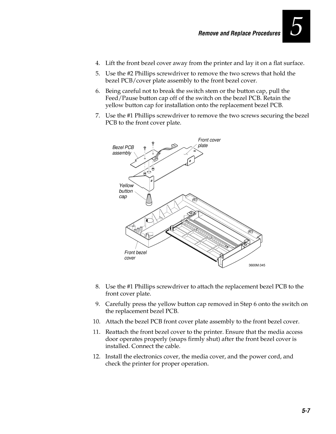
Replacing the Bezel PCB
To replace the bezel PCB assembly
Bezel PCB assembly Yellow button cap
Replacing the Main PCB
To replace the main PCB assembly
To replace the Kanji/Katakana PCB
Replacing the Kanji/Katakana Option PCB
To replace the label mark sensor
Replacing the Label Mark Sensor
3600M.049
To replace the label taken sensor
Replacing the Label Taken Sensor
To replace the label gap sensor
Replacing the Label Gap Sensor
Upper media guide Label gap sensor
To remove the TTR drive roller and TTR drive gear/pulley
Replacing the TTR Drive Roller and Gear/Pulley
Washer Ring
To replace the TTR drive roller and TTR drive gear/pulley
Replacing the TTR Takeup Hub, Clutch/Pulley, and Belt
Remove and Replace Procedures
Replacing the TTR Supply Hub and Adjusting Plate
TTR
To remove the platen roller and platen roller gear
Replacing the Platen Roller and Gear
To replace the platen roller and platen roller gear
To replace the liner takeup hub and liner reverse gear
Replacing the Liner Drive and Takeup Components
Liner reverse gear Thin washer Snap ring
To replace the liner drive roller
Remove and Replace Procedures
Liner drive gear/pulley
To reassemble the liner drive and takeup components
To replace the stepper motor
Replacing the Stepper Motor
To replace the AC plug and input filter
Replacing the AC Plug/Input Filter
To replace the power switch/circuit breaker
Replacing the Power Switch/Circuit Breaker
To replace the transformer
Replacing the Transformer
Printer Maintenance Manual
PCB Drawings and Schematics
Page
PCB Drawings and Schematics
2/10
3/10
4/10
CAP,ALUM,RDL LEAD,50VMIN,100UF
CAP,AL,ELCTLT,R/L,63V,12000UF
CAP,S/M,CER,50WVDC,5%,10 PF
DIODE,S/M,TYPE BAS16
DIODE,S/M,TYPE MMBD301
IC,S/M,TYPE MC68332,MICPRCS
3600M.072
3600M.073
3600M.074
3600M.075
3600M.076
Page
Page
Replacement Parts
Page
Printer Spare Parts List
Replacement Parts
ID No
Part Number
PLATE, Front Cover
BATTERY, Lithium 3.6V, 1.75AH SCREW, THD Roll W/CONE
WASHER, Flat SST .327 X .50 X
Manuals
Page
3600M.091
3600M.092
3600M.093
3600M.094
3600M.095
114
127 125 128 129 130 131 132 133 134
Appendix
Page
Functional Description of the 3600 Mechanics
Functional Description of the 3600 Electronics
Power Supply
+5V
+40V
Battery
Power Fail Detection
Battery Life Calculations
Reset
Motor Driver
Chip Selects
Processor
Crystal
Interrupt Priority Levels
Eprom Access Time
RAM Access Time
Memory
Static RAM
Communications Interface
DIP Switches
Converter
Asic and I/O Option Interface
Front Panel Interface
Option Connector
Debug Interface
Chip Select Generation
Row Name Formula Min Max Margin Comment
Printer Maintenance Manual Timing
Timing Diagram
Functional Description of the 3600 Software
Band Buffering and Font Caching
Image Band Buffering
Image Band Example
Printer Maintenance Manual
Appendix a
Font Caching
Digital Thermal Compensation
Global Compensation
Appendix a Font Caching Flow Chart