J300 Series
Safety
Definitions and Symbols
Precautions
Page
Revision History Table
Iii Pollution degree Aug
Table of Contents
Safety Precautions
Installation
Inputoutput
Bad example
Input phase failure protection
Noise filter Fuse Good example Power supply
Control and operation
Maintenance, inspection and part replacement
Appendix
Turn on and OFF Good example
Megohm-meter
Earth leakage breaker Mgo
Motor
Earth LeakageSurge absorber breaker Power
Supply Leading power factor capacitor
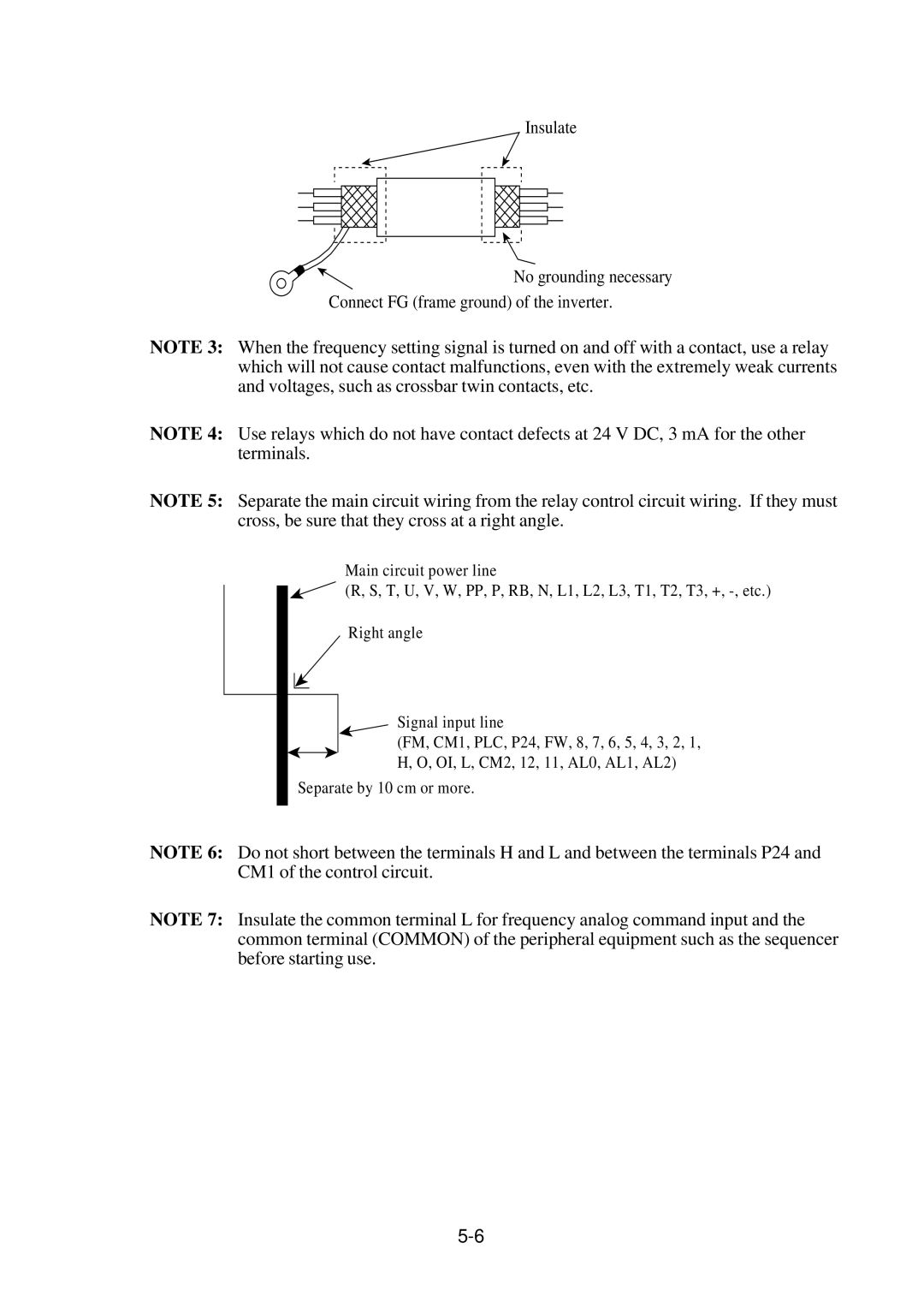
To be grounded or shielded wire
General Caution
Contents of Specifications Label
Inspection Upon Unpacking
Appearance and Names of Parts
Names of Parts
Installation
Be sure to check the ambient temperature
Precaution for installation and wiring
Vent hole Cm or more
Wiring
Power supply
Dynamic Braking Resistor Braking Units
Wiring the Power Supply and Motor
L3 RB + T1 T2 T3 PE
ELB
Improper grounding Proper grounding Inverter
Inverter At the site
CM2 AL2 AL1 AL0
Wiring of Control Circuit Terminals
FM CM1 PLC P24 CM2 AL2 AL1 AL0
Page
Connection to the Programmable Controller
Magnetic
Wiring Equipment, Options EMI filter, etc
Standard equipment Power supply
200V class
Inverter
Terminal
RB P
Common for frequency command Output
Free run input signal
Current frequency command
Run signal 27 VDC Intelligent output signal
Control Circuit Terminals
PLC
Contact rating 250 VAC Resistor load
Abnormal, Power off
AL0-AL1 open
Cosø=0.4 10 mA 30 VDC Resistor load
Terminal Connection Diagram
Operation
Before Starting Operation
Page
Test Run
Running from external command
For sink type wiring
Operating with digital operator
Key to Key to set Press
Key and then press Press
Key to set Press
Key to
Contact specification
Contact b Contact a
Resetting Any one of A, B and C is possible
Operation of the Digital Operator
Power Lamp Monitor LED display
STOP/RESET key
Func Function key Up key, Down key
Key is pressed, the extension function mode can be selected
Key Description
Explanation of Screen Display
Output frequency
Monitor mode
Transition of Each Code
Digital Operator Initialization List
Screen display
Monitor mode contents
Explanation of Modes
Trip cause
10.00 to 100.00 to
Trip current
Is displayed
Frequency
Function mode
Setting
Running
Direction
Accelera- tion time 1 Decelera
Tion time 1 Manual torque boost
Run
Motor receiving voltage setting
Extension function
How to Delete Trip History Data ,
Extension function mode contents
Speed control response constant
Start frequency adjustment
Extension Function Code
Initial value Constant between 99.9 is set in units
Frequency upper, lower limiter
Frequency command sampling frequency setting
Extension Function Code Contents and display
Carrier frequency setting
Multispeed setting
Initial value Func
Setting method 20% 120%
Motor poles setting for motor speed monitor
100 150
400 External frequency
Setting end
Initial value Setting method
Same as A26
T1 + t2 + t3 100 Model 055, 075LF
Operation will be stopped
Inverter requiring an external resistor
External
Torque monitor 200% of the rated torque
Output full-scale value
Current monitor
Terminal connection example
Speed arrival
Frequency arrival signal output method
At the time of constant
Only optionally set frequency
Swjg
Swfw
Frequency at the start of running
Base frequency setting
Maximum frequency
PID
Motor data selection
This function is valid when 0 is set for Setting method
Auto tuning setting
Unusable
Ro-T- option selection
Terminal Setting
Input
Overtorque signal Note As that of the input terminals
Frequency arrival signal
Signal during running Setting method is the same
Extension Function Code Function name
Input
Protection Functions
Other display
Troubleshooting
Error Messages and Diagnosis
BRD%ED
Ground fault on
Check Countermeasure
Symptom
Display on
Appropriate value
Trouble shooting
HRW-OJ
Page
Inspection Items
Maintenance and Inspection
Maintenance and Inspection Precautions
Insulation resistance tests, withstand voltage tests
Bad example Time
10-2
Applied voltage Good example Time Megohm-meter
Instruments
10-3
Daily Inspection and Periodic Inspection 1/3
Location Daily Periodic
10-4
Daily Inspection and Periodic Inspection 2/3
No blown out LEDs
Replacement
Daily Inspection and Periodic Inspection 3/3
Measurement Method for I/O Voltage, Current, and Power
Parts to be measured
10-7
Measurement method for output voltage
11-1
Standard Specifications
Common Standarsd Specifications
11-2
Description Input voltage Class Model Name Type
Individual Specification USA version J300
11-3
12-1
Functions When Using the Optional Remote Operator
Connecting the remote operator
Same as VWA, J100
Switch Model J300 series
12-2
Monitor mode
12-3
12-4
Term Lllllllll
Function mode
12-5
12-6
12-7
12-8
12-9
12-10
12-11
12-12
12-13
12-14
12-15
12-16
For error contents, see
Other displays
12-17
Forced rewriting Description Alarm
Value. Note that when Automatically rewritten
Fmax Fch
12-18
Dimensions
Remote operator, copy unit
Copy Unit Function
12-19
Data to be copied by the copy unit Precautions for copying
12-20
Service
13-1
Page
Autotuning start Setting method
Precautions
Select 1 Control in the second hierarchy
New remote operator
Select 3 Function in the first hierarchy
Select 2 Motor in the third hierarchy
Display in the failure state
Tuning END
Tuning NG
Running method by autotuning data
Select Sensorless vector control by Control method
Select 1 V/f in the third hierarchy
Change the content of 6 Mode from
When the data is changed, press Key
0VC to 4SLV in the fourth hierarchy
Carrier
Large load
50% Range where the energy conservation is effective
Energy conservation running Outline of the function
Initial display
SPD
Precautions
Setting process
Principle
Digital operator Select Running mode selec Tion
STR Mode 2GOD
IPS Powr
IPS Trip OFF
Time chart for retry mode
Alarm
Function mode F-34
Commercial power source switching
Set TRM terminal mode
Digitaloperator
Elbc
Ambient Temperature Hours Operation/day Capacitor life year
Appendix 3 Capacitor Life Curve
RU curve Acceleration
Appendix 4 Acceleration/Deceleration Curve Constants
Curve
Deceleration
Operation conditions
When V/f control is selected Function mode
When sensor-less vector control is selected Function mode
AUX
Motor revolution varies when
Operation conditions Phenomena Improvements Display, etc
Quickly varying load
Load varies
For example, 7.5 kW, 5.5 kW, and 3.7 kW
Select the motor capacity which is the most approxi
Mate to the total capacity of the motors used
AUX K 022.00 kW 005.50 kW Select the most approximate value
Appendix 6 Supplementaly Explanation of the Function Mode
Function name Second function setting
HRW DRW
Monitor mode
HOP, HRW DOP, DRW
1F-SET
4RESET
Initreseton
SET Selectrem
2DATA 0NOR
Controlvc
1AUTO 0NOR
3LINE Acclinel
2TIME
3LINE Decline L
4GAIN Decgain
2FRS 1ZST Runfrs ZST
1LIML
1LEVEL
2CONST1.0
2LIMH
IN-TM3JG
IN-TM1RS
IN-TM2AT
IN-TM4FRS
0EVN
1BAUD
2NUMBER1
1RYA 3RUN
PID Gain
Wiring Sketch
Appendix 8 PID Function
Data Setting Method