Settings Section
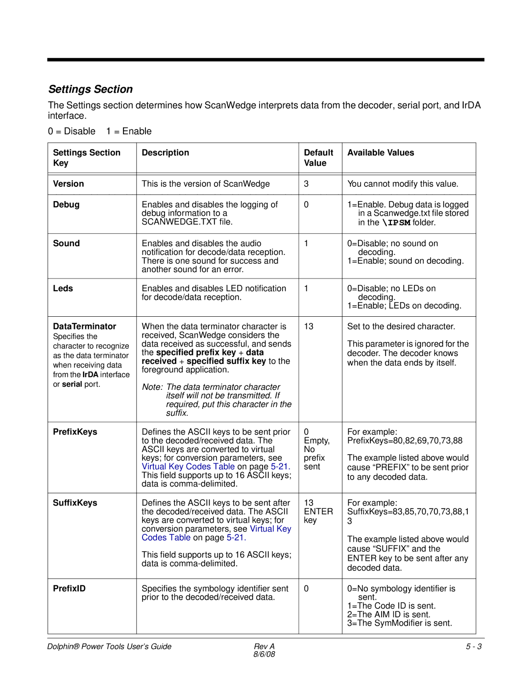
The Settings section determines how ScanWedge interprets data from the decoder, serial port, and IrDA interface.
0 = Disable 1 = Enable
Settings Section | Description | Default | Available Values |
|
Key |
| Value |
|
|
|
|
|
|
|
|
|
|
|
|
Version | This is the version of ScanWedge | 3 | You cannot modify this value. |
|
|
|
|
|
|
Debug | Enables and disables the logging of | 0 | 1=Enable. Debug data is logged |
|
| debug information to a |
| in a Scanwedge.txt file stored |
|
| SCANWEDGE.TXT file. |
| in the \IPSM folder. |
|
|
|
|
| |
|
|
|
|
|
Sound | Enables and disables the audio | 1 | 0=Disable; no sound on |
|
| notification for decode/data reception. |
| decoding. |
|
| There is one sound for success and |
| 1=Enable; sound on decoding. |
|
| another sound for an error. |
|
|
|
|
|
|
|
|
Leds | Enables and disables LED notification | 1 | 0=Disable; no LEDs on |
|
| for decode/data reception. |
| decoding. |
|
|
|
| 1=Enable; LEDs on decoding. |
|
|
|
|
|
|
DataTerminator | When the data terminator character is | 13 | Set to the desired character. |
|
Specifies the | received, ScanWedge considers the |
|
|
|
character to recognize | data received as successful, and sends |
| This parameter is ignored for the |
|
as the data terminator | the specified prefix key + data |
| decoder. The decoder knows |
|
when receiving data | received + specified suffix key to the |
| when the data ends by itself. |
|
from the IrDA interface | foreground application. |
|
|
|
|
|
|
| |
or serial port. | Note: The data terminator character |
|
|
|
|
|
|
| |
| itself will not be transmitted. If |
|
|
|
| required, put this character in the |
|
|
|
| suffix. |
|
|
|
|
|
|
|
|
PrefixKeys | Defines the ASCII keys to be sent prior | 0 | For example: |
|
| to the decoded/received data. The | Empty, | PrefixKeys=80,82,69,70,73,88 |
|
| ASCII keys are converted to virtual | No |
|
|
| keys; for conversion parameters, see | prefix | The example listed above would |
|
| Virtual Key Codes Table on page | sent | cause “PREFIX” to be sent prior |
|
| This field supports up to 16 ASCII keys; |
| to any decoded data. |
|
| data is |
|
|
|
|
|
|
|
|
SuffixKeys | Defines the ASCII keys to be sent after | 13 | For example: |
|
| the decoded/received data. The ASCII | ENTER | SuffixKeys=83,85,70,70,73,88,1 |
|
| keys are converted to virtual keys; for | key | 3 |
|
| conversion parameters, see Virtual Key |
|
|
|
| Codes Table on page |
| The example listed above would |
|
| This field supports up to 16 ASCII keys; |
| cause “SUFFIX” and the |
|
|
| ENTER key to be sent after any |
| |
| data is |
|
| |
|
| decoded data. |
| |
|
|
|
| |
|
|
|
|
|
PrefixID | Specifies the symbology identifier sent | 0 | 0=No symbology identifier is |
|
| prior to the decoded/received data. |
| sent. |
|
|
|
| 1=The Code ID is sent. |
|
|
|
| 2=The AIM ID is sent. |
|
|
|
| 3=The SymModifier is sent. |
|
|
|
|
|
|
|
|
|
|
|
Dolphin® Power Tools User’s Guide | Rev A | 5 - 3 |
| 8/6/08 |
|