Industrial Devices Corporation
PCW-5181
Page
Revision History
Version
Page
Table of Contents
END of Manual
Feature Function
Impulse Overview
This page intentionally left blank
Shipping Contents
This page intentionally left blank
Connecting and Installing Your Impulse
Typical Impulse Applications
Read This Page Before Your Begin
Connecting a Motor to the Impulse
Connecting an IDC Motor
Connecting a Non-IDC Motor
Serial Communication Connections
Making RS-232/RS-485 Connections
SS-RS232
Rules for Daisy Chain Operation
Daisy-Chaining Impulse Drives
Multi-Dropping with RS-485
PC/Host RS-232C Device
Troubleshooting RS-232C Communication Problems
Jumpers Pin D
Using a Keypad with Impulse RS485
Connecting an IDC Keypad
Using a Keypad with Impulse RS232C
FP100 Keypad
Connecting AC Power
LED Diagnostic Indications
Diagnostic LED Indications LED Signal
Connecting Inputs and Outputs
Application Notes
Environmental and Installation Requirements
Mounting the Impulse Drive
Mounting Arrangements
Impulse Dimensions
Impulse with DIN-rail Mounting Bracket P/N PCS-5111
Impulse with Screw-type Mounting Bracket P/N PCS-5110
Inserting and Removing Mounting Brackets from the Impulse
Installation of Bracket DIN Rail Bracket Shown
Installation
Removal
Removal of Impulse from the DIN-Rail
Impulse DIN-Rail Mounting
Mounting the Impulse on the DIN-Rail
Mounting
This page intentionally left blank
Configuring Impulse with Application Developer
Installing Application Developer on Windows 95/98/2000/ME/NT
Using Application Developer
Upload Project
Launch Now
Open an Existing Project
Using the Project Wizard
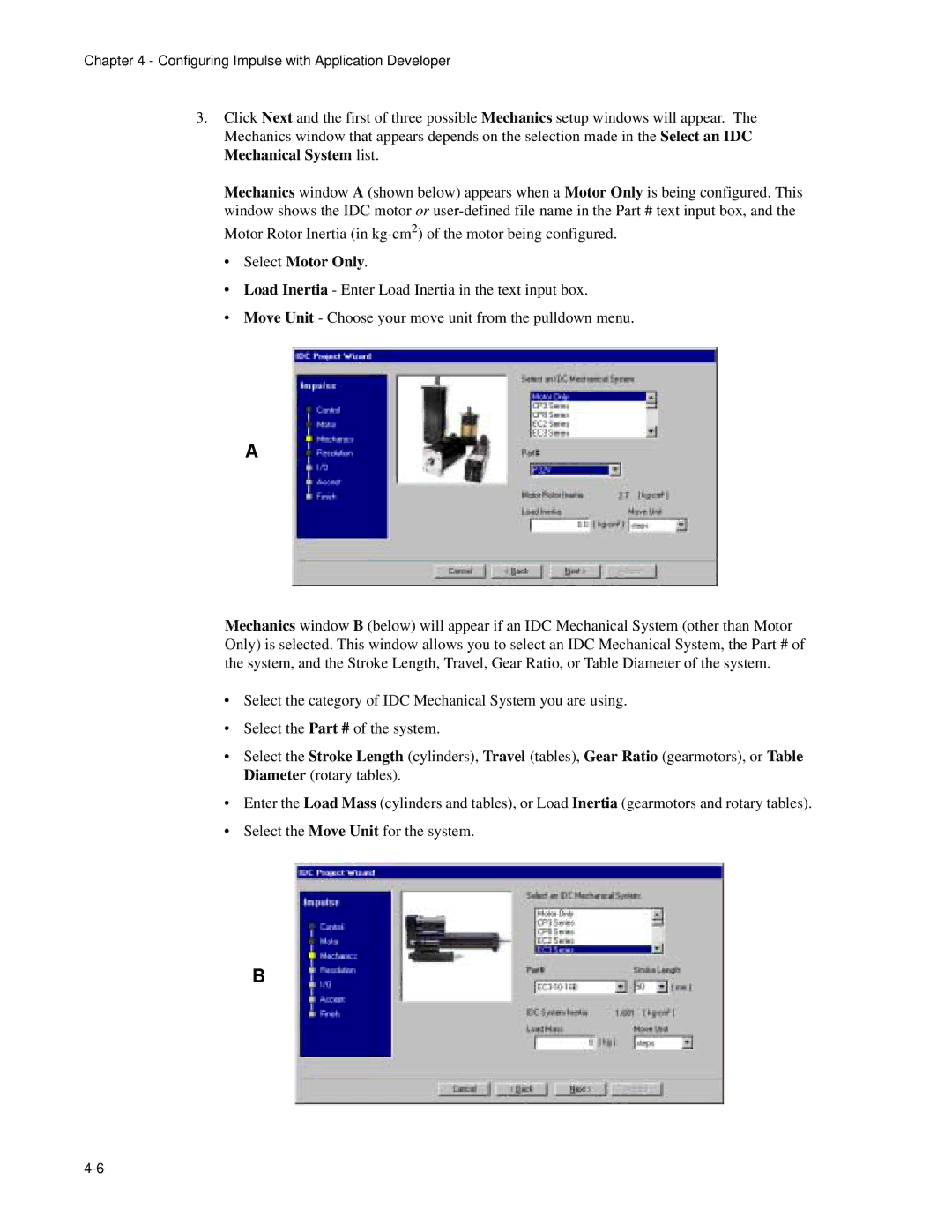
Select Motor Only
Configuring Impulse with Application Developer
Configuring Impulse with Application Developer
Configuring Impulse with Application Developer
Fine-Tuning Your Application
Axis Setup
Toolbar Buttons
Motor
See Appendix C to Edit a Motor
Mechanics
Command
Command Signal Configuration
Jog Input Configuration
Numeric Precision
Adjusting X-Smoothness #1, #2, #3
Smoothness Xtreme Smoothing
Smoothness #1
Smoothness #2
Smoothness #3
Anti-Resonance
Advanced Advanced Tuning
Current Reduction Mode
Profiling
Setup
Descriptions Input Descriptions
Stall Detection
Inactive
Output Descriptions
Stored Move Setup Editing Stored Moves
Configuring Impulse with Application Developer
Setup Menu
File Menu
Edit Menu
Communications Menu
Run Menu
View Menu
Updating Your Impulse Operating System
This page intentionally left blank
Configuring Impulse with an IDC Keypad
Keypad Features
Introduction to the FP100 Impulse Keypad
DIP Switch Settings
Keypad Hardware Features
Adjusting Contrast
Remote-Mounting the Keypad
RUN Menu Keys
Functions of the FP100 Keypad Keys
Keys F1-F2-F3
Keys
FP100 Main Menu and Sub-Menus
Keypad Menu Structure
Menu Options
JOG F3
Apply Power to the Keypad
General Rules for Using the Keypad
RUN Using the RUN Menus
Opening a Project File
Edit Using the Edit Menus
File Menu File Options
Saving a Project File
Renaming an Open Project File
Using the Setup Sub-Menus for Configuring Your System
Sub-Menu Setup Parameter Description of Setup Parameter
Requires Open File
Help Using the Help Menu
Copy Using the Copy Menu
DEL Using the DEL Delete menu
To Delete a Project File
Parameter Being Configured example Motor Type
−−−↑ Motor Type ↓−−− None
Configuring Motor Type
Configuring Impulse with the Keypad
Using the Edit Setup Menus to Configure the Impulse
Open a File
Configuring Motor Direction
Configuring Shutdown Polarity
To Probe the Motor
Configuring Jog Parameters
Configuring Drive Resolution
Configuring Stop Rate
Drive Resolution 25000
User Units
Configuring Mechanical Units User Units
Configuring Units Gear Ratio
Units Gear Ratio Numerator
Motor Tuning Setup X-Smoothness
↑ X-Sm1 L1 Value ↓ ↑ X-Sm1 L2 Value ↓ Sm1 Test Speed RPS
L2 ←
Configuring Anti-Resonance Gain
Configuring Profiling Parameters
Configuring Stop Mode Current-Reduction Timeout I-STOP
Idle Mode Tmeout Off Idle Mode %Redct
Configuring Idle Mode Current Reduction Parameters
Configuring Encoderless Stall-Detection Olsd
Stall Detection
Configuring Inputs
Setup
←↑ Input #1 ↓→
Configuring Outputs
Configuring Input/Output Polarities
↑ Output #1 ↓
Move Menus Using Stored Moves
Stored-Move Profiles
Stored Moves
Move Selection Input Scan Time
Configuring Stored-Move Profiles
Configuring Scan Time
Move Sel Scan Time 0 ms
Very Important! Send the File to the Drive
Unit Number
Impulse Specifications
Hardware Reference
Remote Mounting Your Keypad
Extending the Cable Length to Your Keypad
End View of Wall-Mounted Keypad with Cover Removed
Keypad Mounting *Template
Keypad Mounting Template
Impulse I/O Schematics
Digital Inputs
Digital Output
Differential Installation
Fault Output
Single-Ended Installation
Step, Direction, and Shutdown Inputs
RPS-1
Accessory P/N & Description
SS-RS232
PCS-5004
Pin Connector on Impulse Drive
DB25BO Screw Terminal Breakout Board
SS-IO/SS-IO-6 Cables
Electrical Specs S12T
Impulse-Applicable IDC Motors
S12 Hybrid Step Motor
Mechanical Specs S12T
Electrical Specs S21T S21V S22T S22V S23T S23V
S21, S22, S23 Hybrid Step Motor Specifications
IDC Motor Wiring
S22T S22V S23T
S32, S33 Hybrid Step Motor Specifications
Electrical Specs S32T S33T
S32T S33T
P21, 22 Hybrid Step Motor Specifications
Electrical Specs P21V P22V
P21V P22V
31, 32, 33Step Motor Specifications
IDC Motor Wiring
This page intentionally left blank
Troubleshooting the Impulse
Troubleshooting Table
Symptom Possible Causes Possible Remedies
Troubleshooting Your Impulse
Limits Tables
This page intentionally left blank
Product Support
Warranty & Repairs
Appendix a Recommended Wiring Practices for IDC Controls
Preventing a Ground Loop
Appendix a Recommended Wiring Practices
Appendix B Impulse Advanced Programming
Communications Protocol
Receive Buffer Overrun
Reading and Writing Parameter Data
Byte Receive Time Out
Read Queries
01 71 00 00 00 00 72
Write Requests
Interpreting the Transmission Status Response
01 00 00 00 01
User Accessible Parameters
Serial Jog Velocity RAM Only
Jog Acceleration Rate
Description Determines the acceleration rate value in RPS2
Parameters
28h
Formulas
Serial Port Stored Move Selection RAM Only
Formula
Commanded Velocity RAM Only
Formulas N/A Index
Stored Drive Faults Reserved Eeprom Parameter
Commanded Position Counter RAM Only
Formulas N/A Index Parameter Description
Eeprom Enable Switch
System Status RAM Only
Description Determines the operational status of the drive
Parameters
Defaults
Unit Address
Formulas
Software Shutdown RAM Only
Parameter Formula
Appendix C Using Non-IDC Motors with the Impulse
Motor Wiring
Custom or User-Defined Motors
Test Speeds 1, 2
Smoothness L1 and L2
Dynamic Smoothing
Anti -Resonance
Faults
Index
Index
Do Not Print This Inserted as Placeholder
Industrial Devices Corporation
Mail info@idcmotion.com