101
Biases and gains of speed setting terminals
Thank you for choosing this Mitsubishi Vector Inverter
102
Electric Shock Prevention
Trial run
Transportation and installation
Wiring
Operation
Disposing of the inverter
Maintenance, inspection and parts replacement
Emergency stop
General instructions
Product check and name of parts
Abbreviations
Harmonic Suppression Guideline
Front view
Basic configuration and connection of peripheral devices
Basic configuration and connection of peripheral devices
Basic configuration
200V class
Select the NFB type according to the power supply capacity
Selection of peripheral devices
400V class
Structure
Removal and reinstallation of the front cover
Reinstallation
Structure
Reinstallation using the connection cable
Structure Removal and reinstallation of the operation panel
Reinstallation
Installation of the inverter
Installation of the inverter
Install the inverter under the following conditions
Connection diagram, PLG cable, PU connector
Connection diagram, PLG cable, PU connector
Connection diagram
Specification of main circuit terminal
Connection diagram, PLG cable, PU connector Main circuit
Terminal Symbol Terminal Name Description
Terminal arrangement of the main circuit terminal
Screw size M8
400V class
Screw size M6
400V class When input power supply is
Cables and wiring length
200V class When input power supply is
Cable gause for the control circuit power
PLG output circuit jumper connector
Setting the PLG
Type Length L m
Parameter Name Factory Setting Setting Range Remarks
Pr Setting Relationship between the motor and PLG
Specifications of control circuit terminals
Connection diagram, PLG cable, PU connector Control circuit
Type Terminal Terminal Name Description Symbol
Not output during inverter reset
Wiring instructions
Control circuit terminal layout
Changing the control logic
When using an external power supply for transistor output
For computer link communication
Parameter Name Factory Setting Setting Range
Setting the m otor
Setting the motor
Dedicated motor SF-V5R 1500r/min series
At-a-glance guide to motor setting
When using other manufacturers’ motors
Precautions for use of the vector inverter
Precautions for use of the vector inverter
Motor Rated Voltage
Checks prior to test run
Basic operation Speed setting, run, speed meter adjustment
Setting the speed and running the motor
Checks prior to test run
PU jog operation
Basic operation Speed setting, run, speed meter adjustment
Turn on the start switch STF or STR
Operation status indication FWD or REV flickers
External jog operation
It may take some time until the pointer moves
Changing example
Display the present operation speed by pressing SET to
To stop the inverter
Key indication
Names and functions of the operation panel
Names and functions of the opera- tion panel
Unit indication, operation status indication
Alarm *1 absent
Speed setting
Used to set the running speed in the PU operation mode
Monitoring
Operation mode
Once, press SET , and restart the setting from the beginning
Alarm history
Names and functions of the opera- tion panel Help mode
Alarm history clear Clears all alarm history
Parameter clear
All clear
Names and functions of the opera- tion panel Copy mode
Parameter setting mode
Speed control operation
Setting procedure
Speed control operation
Speed control
Speed command
Speed control operation Operation command setting
Forward and reverse rotation commands terminals STF, STR
Torque restriction
Torque restriction level
Second torque restriction level
Torque restrictions during acceleration and deceleration
Gain adjustment
Preset speed-speed
Pr deceleration torque
Torque control operation
When 0 is set in Pr or Pr acceleration/deceleration time
Torque control operation
Torque control
Signal Terminal Name Remarks
O signals
Following table indicates the operations of the signals
Operation example Pr =0
Torque command setting
Torque control operation Setting procedure
Torque command right selection
Perform secure wiring. Refer to Set the PLG. Refer to
Speed restriction
Used to give a speed restriction command
When Pr =
10E +10V
Position control operation
Position command from parameter setting
Position command from PLC
Position control operation
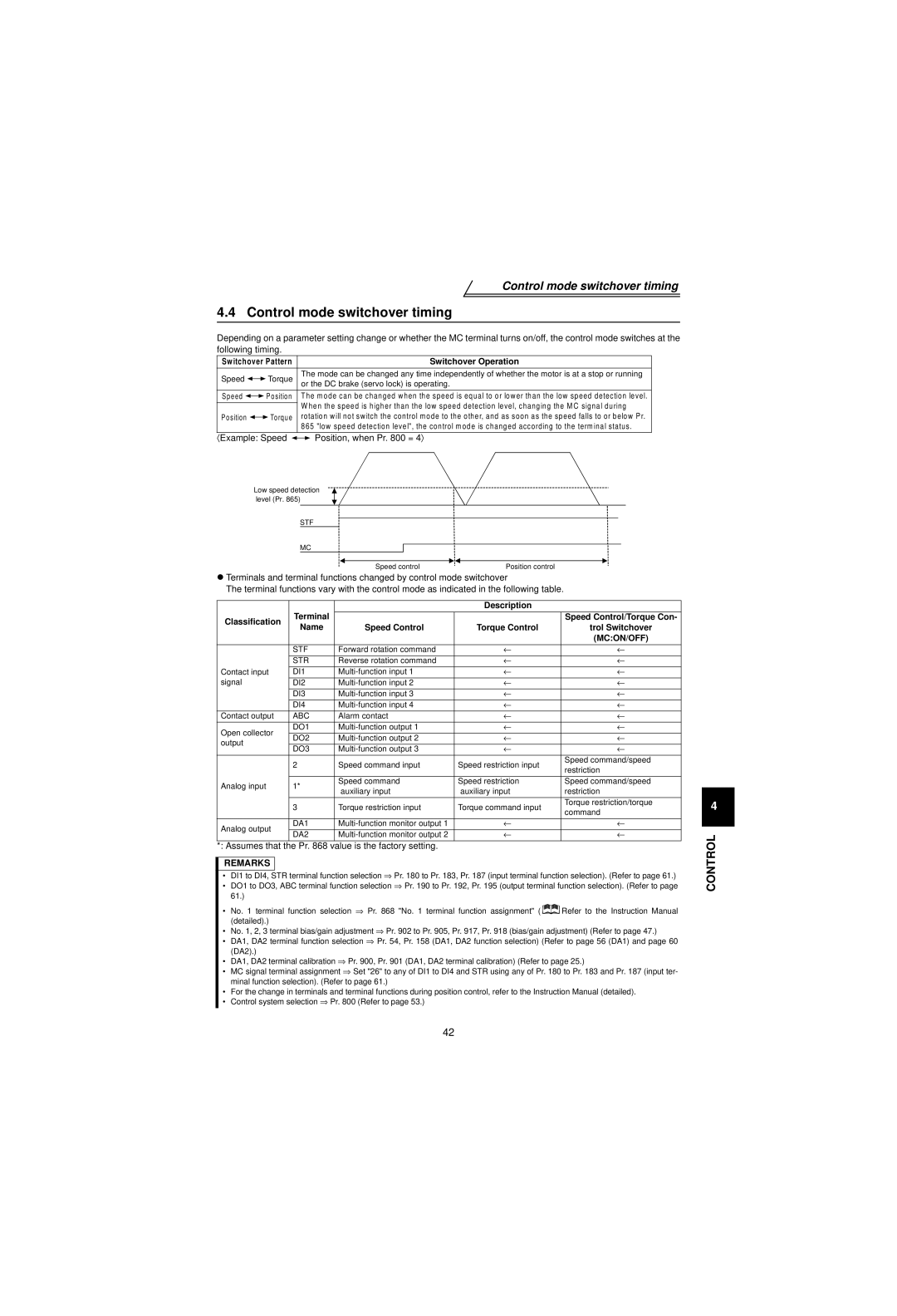
〈 Example Speed Position, when Pr = 4〉
Control mode switchover timing
Control mode switchover timing
Assumes that the Pr value is the factory setting
Easy gain tuning execution procedure
Easy gain tuning
Easy gain tuning
Start signal
Checking the Pr control system selection value
Easy gain tuning Precautions for easy gain tuning
Automatically set parameters by easy gain tuning
Load inertia estimation restriction conditions
Page
2 Pr =1 start-time tuning
Online auto tuning
Online auto tuning
3 Pr = 2 normal tuning/adaptive magnetic flux observer
Torque %
Setting
Output speed
10V
Setting change 1.5 s
Read Pr to display the currently set gain speed
Example When the analog
Current analog voltage adjustment value
Value is 100%
Function list Simple mode parameters
Function list Simple mode parameters
Simple mode parameter list
Refer to page 62 for Pr soft PW M control
Setting Carrier Frequency
You can change the motor sound
Pr maximum speed, Pr minimum speed
Refer to page 46 for details
Pr extended function display selection
Setting Drive System Control Method Remarks
Refer to page 43 for details
Pr control system selection
Function list Extended function parameters
Function list Extended function parameters
Speed jump 1A
Deceleration pattern
Regenerative
Speed jump 1B
Alarm occurrence
Remote setting
Intelligent mode
DA1 terminal function
Applied motor
Speed setting signal
PWM frequency Selection
Operation mode
Reset selection
Parameter write Disable selection Reverse rotation
Online auto tuning Selection Auto tuning setting
Switchover
123 Waiting time setting
144 Speed setting
117 Station number
Power failure
157 OL signal output
Timer
Stall prevention 156 Operation selection
171 Actual operation hour
Maker setting parameters. Do not make setting 169
168
Meter clear DI1 terminal function
234 Multi-speed setting
232 Multi-speed setting
Multi-speed setting 233
236 Multi-speed setting
Command 357 In-position zone
Command selection
Switchover speed
286 Droop gain
Command filter
Position command
Command pulse 420 Scaling factor Numerator
427 Excessive level error
465 First position feed
Digital position
464 Control sudden stop
Amount lower 4 digits
805 Torque command
Selection 801 Torque characteristic
Characteristic
Value RAM Torque command
826 Torque setting filter
818 Easy gain tuning Response level setting 819
822 Speed setting filter
832 Speed setting filter
841 Torque bias
Adjustment
840 Torque bias selection
842 Torque bias
890 Maintenance output
874 OLT level setting
Fault definition
Setting time 892 Maintenance output
Errors Alarms
Errors Alarms
Major faults
Motor Overload
OV During Acc
OV During Dec
Inv. Overload
Inst. Pwr. Loss
Br. Cct. Fault
Ground Fault
Under Voltage
Option slot alarm 1 to
OH Fault
Option Fault
Stll Prev STP OL shown during stall
Corrupt Memry
Fault 1 to Fault
CPU Fault
PU Leave Out
Operation Panel P24
Fault
Indication Fault Name
Operation Panel P12
No encoder a signal
No encoder signal
Excessive position error
Overspeed occurrence
Fan Failure
Minor fault
Stall prevention
Operation Panel Err Indication
Errors Alarms How to recover from PU stop error PS
Reset from operation panel
Correspondences between digital and actual characters
Resetting the inverter
Correspondences between digital and actual characters
Memo
Motor generates abnormal noise
Troubleshooting
Troubleshooting
Vector control
Troubleshooting Motor does not rotate
Vector control
For speed restriction?
Command been
Is the torque
Parameter
F control
Troubleshooting Motor generates heat abnormally
Speed control
Troubleshooting Motor hunts
Being made?
Troubleshooting Machine operates unstably
Have you set the motor type? Is the PLG setting correct?
Troubleshooting Speed command does not match motor speed
Does the inverters speed command match the motor speed?
Troubleshooting Motor rotates but speed does not change
Torque control
Troubleshooting Torque control is not exercised normally
Is the wiring length short?
Pr , Pr Is an external
Frequency low?
Is the torque command unvaried?
Reduce noise
Filter Pr
Insulation resistance test using megger
Precautions for maintenance and inspection
Precautions for maintenance and inspection
Check items
Daily and periodic inspection
Precautions for maintenance and inspection Pressure test
Do not conduct a pressure test. Deterioration may occur
Interval
Replacement of parts
Part Name Standard Replacement Interval Description
Area Inspection Description
Smoothing capacitors
Cooling fan
Relays
Measurement of main circuit voltages, currents and powers
Examples of Measuring Points and Instruments
100%
Measuring Points and Instruments
100% Pf1 =
Pf2 =
Model specifications
Model specifications
10.0 12.8 19.0 24.6 30.4 35.8 46.3 59.5 68.5 91.0
Three-phase, 380 to 480V 50Hz/60Hz
Three-phase, 380V to 480V 50Hz/60Hz
10.0 14.5 18.5 27.5 35.5 51.8 132
Common specifications
Common specifications
Inverter outline dimension drawings
Outline dimension drawings
Outline dimension drawings
FR-V520-1.5K‚ 2.2K FR-V540-1.5K‚ 2.2K
FR-V520-18.5K
FR-V520-11K‚ 15K FR-V540-7.5K‚ 11K, 15K, 18.5K
250
FR-V520-22K, 30K‚ 37K !FR-V540-22K, 30K‚ 37K
Inverter Type
SF-V5RH 1K
SF-V5RH 2K ‚ 3K
SF-V5RH 5K ‚ 7K
SF-V5RH 30K ‚ 37K ‚ 45K ‚ 55K
110
For Maximum Safety
Print Date Manual Number Revision

 Position, when Pr. 800 = 4〉